145
Precautions The PVs of totalizing timers in interlocked program sections are maintained
when the execution condition for IL(02) is OFF. Unlike timers and high-speed
timers,
totalizing timers in jumped program sections do not continue timing, but
maintain
the PV
.
Power interruptions will reset timers.
Totalizing timers will not restart after timing out unless the PV is changed to a
value below the SV or the reset input is turned ON.
A
delay of one cycle is sometimes required for a Completion Flag to be turned
ON after the timer times out.
The
SV of the timers can be set in the range #0000 to #9999 (BCD). If the SV for a
timer
is set to #0000 or #0001, it will operate in the following way
. If the
SV is set
to
#0000, when the timer input
goes from OFF to ON, the Completion Flag will
turn
ON. If the SV is set to #0001, because the timer accuracy is 0 to –0.1 s, the
actual time will be a value between 0 and 0.1 s, and the Completion Flag may
turn
ON as soon as the timer input goes from OFF to ON. With other values also,
allow for a timer accuracy of 0 to –0.1 s when setting the SV.
Flags ER (SR 25503):Content of ∗DM word is not BCD when set for BCD.
SV is not BCD.
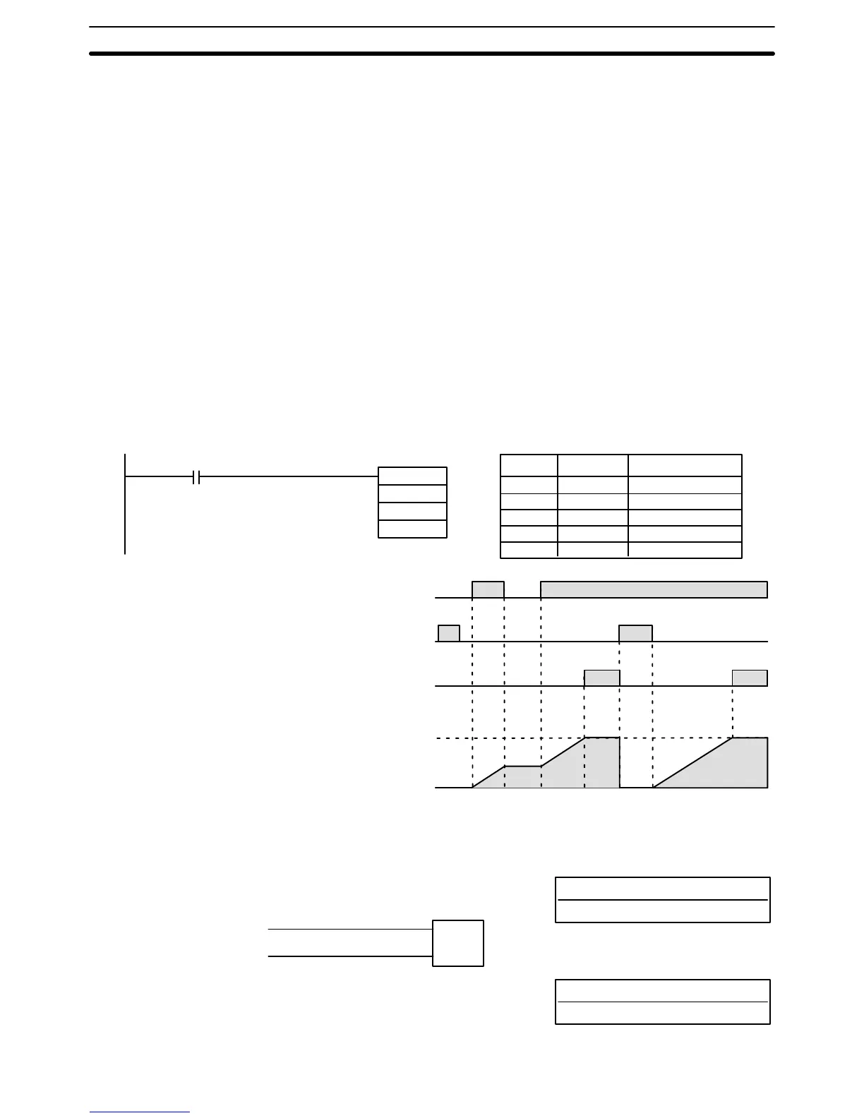
Example The
following figure illustrates the
relationship between the execution conditions
for a totalizing timer with a set value of 2 s, its PV, and the Completion Flag.
Address Instruction Operands
00000 LD 00000
00001 TTIM(87)
TIM 000
# 0020
LR 2100
00000
TTIM(87)
TIM 000
#0020
LR 2100
Timer
input
(I: IR 00000)
Reset bit
(RB: LR 2100)
Completion Flag
(TIM 000)
Present value: 0020
0000
5-14-4 COUNTER – CNT
N: TC number
# (000 through 511)
Ladder Symbol
Definer Values
SV: Set value (word, BCD)
IR, AR, DM, HR, LR, #
Operand Data Areas
CP
R
CNT N
SV
Timer and Counter Instructions Section 5-14