303
2. The 7-segment display may require either positive or negative logic, de-
pending on the model.
3. The
7-segment display must have 4 data signal lines and 1 latch signal line
for each digit.
Using the Instruction If
the first word holding the data to be displayed
is specified at S, and the output
word
is specified at O, and the SV taken from the table below is specified at C,
then operation will proceed as shown below when the program is executed. If
only four digits are displayed, then only word S will be used.
Data Storage Format
Leftmost 4 digits Rightmost 4 digits
S+1 S
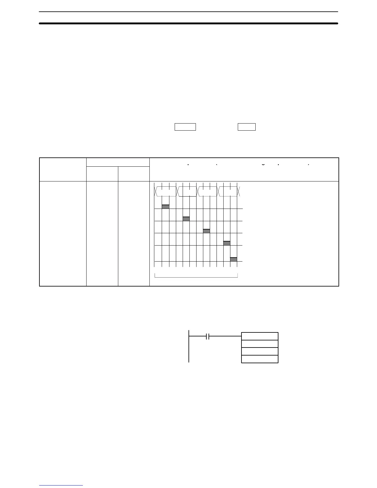
Timing The
timing of data output is shown in the following table. “O” is the first word
hold
-
ing display data and “C” is the output word.
Function
Bit(s) in O
Output status (Data and latch logic depends on C)
(4 digits,
1 block)
(4 digits,
2 blocks)
Latch output 2
Latch output 3
One Round Flag
Latch output 1
Latch output 0
Data output
06
07
08
05
04
00 to 03
10
11
12
09
08
00 to 03
04 to 07
10
0
10
1
10
2
10
3
0123456789101112
Note 0 to 3: Data output for word S
4
to 7: Data output
for word S+1
12
cycles required to complete one round
Application Example This
example shows a program for
displaying 8-digit BCD numbers at a 7-seg
-
ment LED display. Assume that the 7-segment display is connected to output
word
IR 100. Also
assume that the Output Unit is using negative logic, and that
the
7-segment display logic is also
negative for data signals and latch signals.
7SEG(––)
DM0120
100
004
25313 (Always ON)
The
8-digit BCD data in DM 0120 (rightmost 4 digits) and DM 0121 (leftmost 4
digits) are always displayed by means of 7SEG(––). When the contents of
DM 0120 and DM 0121 change, the display will also change.
Flags ER: S and S+1 are not in the same data area. (When set
to display 8-digit
data.)
Indirectly
addressed DM word
is non-existent. (Content of *DM word is
not BCD, or the DM area boundary has been exceeded.)
There is an error in operand settings.
25409: SR 25409 will be ON while 7SEG(––) is being executed.
Advanced I/O Instructions Section 5-28