EasyManua.ls Logo

Omron SYSMAC C200HS User Manual

Omron SYSMAC C200HS
503 pages
To Next Page IconTo Next Page
To Previous Page IconTo Previous Page
Page #151 background imageLoading...
Page #151 background image
141
There are two ways to achieve timers that operate for longer than 999.9 sec-
onds.
One method is
to program consecutive timers, with the Completion Flag of
each
timer used to activate the next timer
. A simple example with two 900.0-sec
-
ond (15-minute) timers combined to functionally form a 30-minute timer.
00000
TIM 001
TIM 002
00200
900.0 s
900.0 s
TIM 001
#9000
TIM 002
#9000
Address Instruction Operands
00000 LD 00000
00001 TIM 001
# 9000
00002 LD TIM 001
00003 TIM 002
# 9000
00004 LD TIM 002
00005 OUT 00200
In this example, 00200 will be turned ON 30 minutes after 00000 goes ON.
TIM
can also be combined with CNT or CNT can be used to count SR area clock
pulse
bits to produce longer timers. An example is provided in
5-14-4 COUNTER
– CNT.
TIM
can be combined with KEEP(1
1) to delay turning a bit ON and OFF in refer
-
ence
to a desired execution condition.
KEEP(1
1) is described in
5-9-4
KEEP –
KEEP(11).
To create delays, the Completion Flags for two TIM are used to determine the
execution
conditions for
setting and reset the bit designated for KEEP(1
1). The
bit whose manipulation is to be delayed is used in KEEP(11). Turning ON and
OFF
the bit designated for KEEP(1
1) is
thus delayed by the SV for the two TIM.
The two SV could naturally be the same if desired.
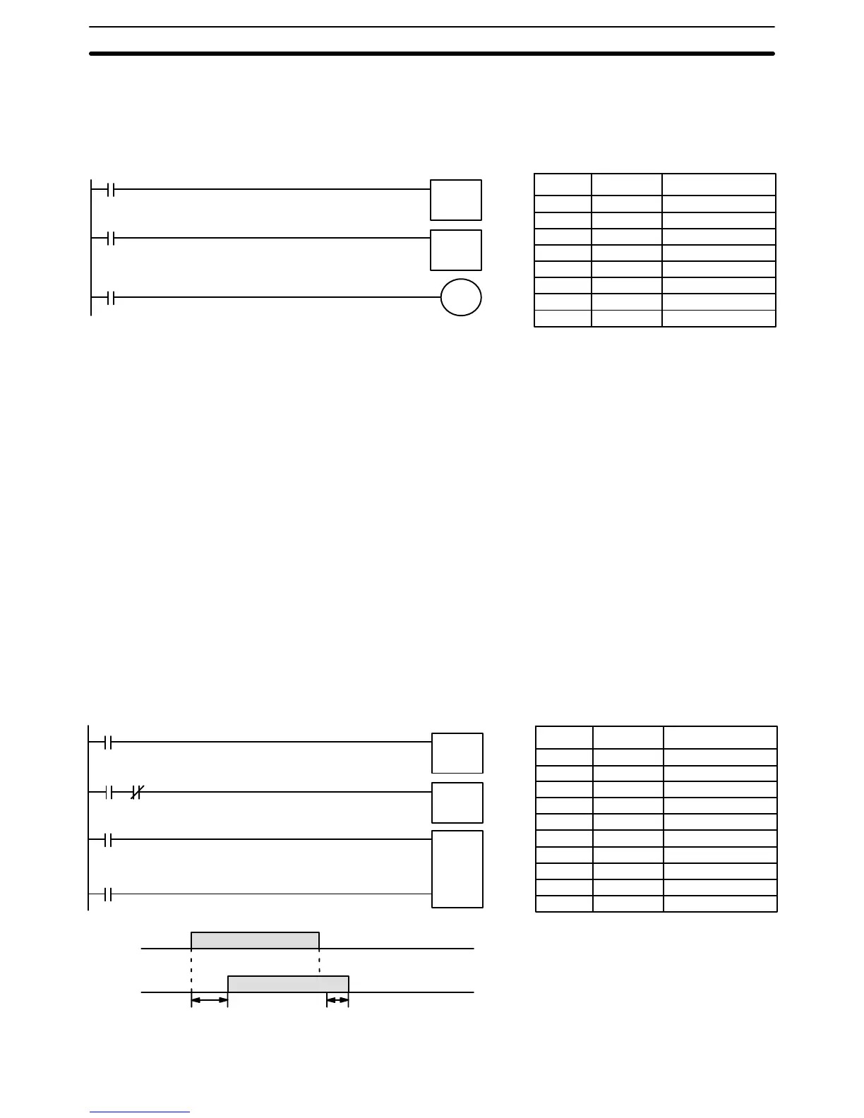
In the following example, 00500 would be turned ON 5.0 seconds after 00000
goes
ON and then
turned OFF 3.0 seconds after 00000 goes OFF
. It is neces
-
sary
to use both 00500 and 00000 to determine the execution condition for TIM
002;
00000 in an inverse
condition is necessary to reset TIM 002 when 00000
goes ON and 00500 is necessary to activate TIM 002 (when 00000 is OFF).
00000
00500 00000
TIM 001
TIM 002
005.0 s
003.0 s
00000
00500
5.0 s
3.0 s
TIM 001
#0050
S
R
KEEP(11)
00500
TIM 002
#0030
Address Instruction Operands
00000 LD 00000
00001 TIM 001
# 0050
00002 LD 00500
00003 AND NOT 00000
00004 TIM 002
# 0030
00005 LD TIM 001
00006 LD TIM 002
00007 KEEP(11) 00500
Example 2:
Extended Timers
Example 3:
ON/OFF Delays
Timer and Counter Instructions Section 5-14

Table of Contents

Other manuals for Omron SYSMAC C200HS

Questions and Answers:

Omron SYSMAC C200HS Specifications

General IconGeneral
ModelC200HS
ManufacturerOmron
SeriesSYSMAC
Humidity10 to 90% RH (non-condensing)
Programming LanguageLadder logic
Program MemoryRAM/EPROM/EEPROM
Communication ProtocolsSYSMAC LINK, SYSMAC NET
Communication PortsRS-232C, RS-422
Power Supply100-240V AC, 24V DC
Operating Temperature0 to 55°C
Vibration Resistance10 to 57 Hz, 0.075mm amplitude

Summary

SECTION 1 Introduction

1-1 Overview

Provides a general introduction to Programmable Controllers (PCs), their operation, and programming concepts.

SECTION 2 Hardware Considerations

2-1 CPU Components

Details the main components of the C200HS CPU, including indicators, fuses, and connection ports.

SECTION 3 Memory Areas

SECTION 4 Writing and Inputting the Program

4-4 Basic Ladder Diagrams

Introduces fundamental concepts of ladder diagram programming, including rungs, conditions, and instructions.

4-7 Inputting, Modifying, and Checking the Program

Details the procedures for entering, editing, checking, and debugging programs using the Programming Console.

SECTION 5 Instruction Set

5-8 Ladder Diagram Instructions

Details fundamental instructions used in ladder diagrams like LOAD, AND, OR, and their variations.

SECTION 6 Program Execution Timing

6-4 I/O Response Time

Details the time taken for the PC to respond to input signals and produce output signals.

SECTION 7 Program Monitoring and Execution

7-1 Monitoring Operation and Modifying Data

Covers procedures for observing and modifying PC data like bits, words, timers, and counters.

SECTION 8 Communications

8-2 Parameters for Host Link and RS-232C Communications

Details essential PC Setup parameters required for enabling Host Link and RS-232C communications.

SECTION 10 Troubleshooting

10-4 Error Messages

Lists common error messages, their probable causes, and possible corrections for diagnosing system problems.

SECTION 11 Host Link Commands

11-3 Host Link Commands

Details the various commands used for host computer communication with the C200HS PC.

Appendix B Programming Instructions

Appendix D Memory Areas

Appendix E PC Setup

RS-232C Port Settings (DM 6645 to DM 6649)

Details the specific parameters for configuring the RS-232C port, essential for communication setup.

Related product manuals