EasyManua.ls Logo

Omron SYSMAC C200HS User Manual

Omron SYSMAC C200HS
503 pages
To Next Page IconTo Next Page
To Previous Page IconTo Previous Page
Page #218 background imageLoading...
Page #218 background image
!
208
Flags ER: Mi and/or Su is not BCD.
Indirectly
addressed DM word
is non-existent. (Content of
DM word is
not BCD, or the DM area boundary has been exceeded.)
CY: ON when the result is negative, i.e., when Mi is less than Su plus CY.
EQ: ON when the result is 0.
Caution Be
sure to clear the carry flag with CLC(41) before executing SUB(31) if its previous status is not
required,
and check the status of CY after doing a subtraction with SUB(31).
If CY is ON as a result
of
executing SUB(31) (i.e., if the result is negative), the result is output as the 10’
s complement of
the true answer. To convert the output result to the true value, subtract the value in R from 0.
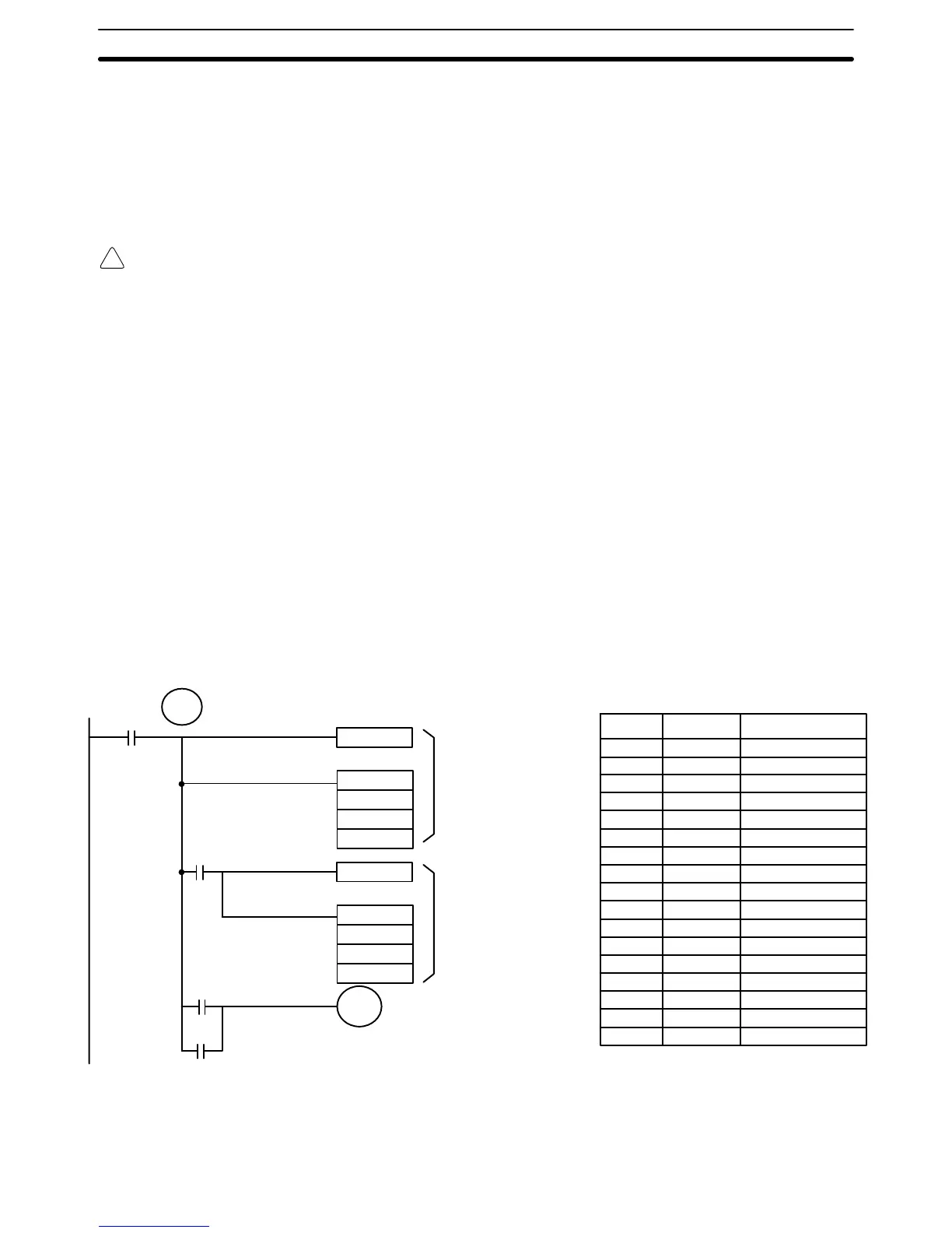
Example When
00002 is ON, the following ladder program clears CY
,
subtracts the con
-
tents
of DM 0100 and
CY from the content of 010 and places the result in HR 20.
If CY is set by executing SUB(31), the result in HR 20 is subtracted from zero
(note that CLC(41) is again required to obtain an accurate result), the result is
placed
back in HR 20, and HR 2100 is turned ON to indicate a negative result.
If
CY is not set by executing SUB(31), the result is positive, the second subtrac
-
tion
is not
performed, and HR 2100 is not turned ON. HR 2100 is programmed as
a self-maintaining bit so that a change in the status of CY will not turn it OFF
when the program is recycled.
In
this example, dif
ferentiated forms of SUB(31) are used so that the subtraction
operation
is
performed only once each time 00002 is turned ON. When another
subtraction
operation
is to be performed, 00002 will need to be turned OFF for at
least one cycle (resetting HR 2100) and then turned back ON.
CLC(41)
@SUB(31)
010
DM 0100
HR 20
CLC(41)
@SUB(31)
#0000
HR 20
HR 21
TR 0
25504
HR 2100
00002
25504
HR 2100
First
subtraction
Second
subtraction
T
urned ON to indicate
negative result.
00000 LD 00002
00001 OUT TR 0
00002 CLC(41)
00003 @SUB(31)
010
DM 0100
HR 20
00004 AND 25504
00005 CLC(41)
00006 @SUB(31)
# 0000
HR 20
HR 20
00007 LD TR 0
00008 AND 25504
00009 OR HR 2100
00010 OUT HR 2100
Address Instruction Operands
The
first and second subtractions for this diagram are shown below using exam
-
ple data for 010 and DM 0100.
BCD Calculations Section 5-19

Table of Contents

Other manuals for Omron SYSMAC C200HS

Questions and Answers:

Omron SYSMAC C200HS Specifications

General IconGeneral
ModelC200HS
ManufacturerOmron
SeriesSYSMAC
Humidity10 to 90% RH (non-condensing)
Programming LanguageLadder logic
Program MemoryRAM/EPROM/EEPROM
Communication ProtocolsSYSMAC LINK, SYSMAC NET
Communication PortsRS-232C, RS-422
Power Supply100-240V AC, 24V DC
Operating Temperature0 to 55°C
Vibration Resistance10 to 57 Hz, 0.075mm amplitude

Summary

SECTION 1 Introduction

1-1 Overview

Provides a general introduction to Programmable Controllers (PCs), their operation, and programming concepts.

SECTION 2 Hardware Considerations

2-1 CPU Components

Details the main components of the C200HS CPU, including indicators, fuses, and connection ports.

SECTION 3 Memory Areas

SECTION 4 Writing and Inputting the Program

4-4 Basic Ladder Diagrams

Introduces fundamental concepts of ladder diagram programming, including rungs, conditions, and instructions.

4-7 Inputting, Modifying, and Checking the Program

Details the procedures for entering, editing, checking, and debugging programs using the Programming Console.

SECTION 5 Instruction Set

5-8 Ladder Diagram Instructions

Details fundamental instructions used in ladder diagrams like LOAD, AND, OR, and their variations.

SECTION 6 Program Execution Timing

6-4 I/O Response Time

Details the time taken for the PC to respond to input signals and produce output signals.

SECTION 7 Program Monitoring and Execution

7-1 Monitoring Operation and Modifying Data

Covers procedures for observing and modifying PC data like bits, words, timers, and counters.

SECTION 8 Communications

8-2 Parameters for Host Link and RS-232C Communications

Details essential PC Setup parameters required for enabling Host Link and RS-232C communications.

SECTION 10 Troubleshooting

10-4 Error Messages

Lists common error messages, their probable causes, and possible corrections for diagnosing system problems.

SECTION 11 Host Link Commands

11-3 Host Link Commands

Details the various commands used for host computer communication with the C200HS PC.

Appendix B Programming Instructions

Appendix D Memory Areas

Appendix E PC Setup

RS-232C Port Settings (DM 6645 to DM 6649)

Details the specific parameters for configuring the RS-232C port, essential for communication setup.

Related product manuals