EasyManua.ls Logo

Omron SYSMAC C200HS User Manual

Omron SYSMAC C200HS
503 pages
To Next Page IconTo Next Page
To Previous Page IconTo Previous Page
Page #246 background imageLoading...
Page #246 background image
236
On
the N
th
cycle, the previous value of S is written to last word in the range D+2 to
D+N+1.
The average value of the
previous values stored in D+2 to D+N+1 is cal
-
culated
and written to D, bit 15 of D+1 is turned ON, and the previous value point
-
er
(the first 2 digits of D+1) is reset to zero. Each time that A
VG(––) is executed,
the
previous value of S overwrites the content of the word indicated by the point
-
er
and the new average value is calculated and written to D. The pointer will be
reset again after reaching N–1.
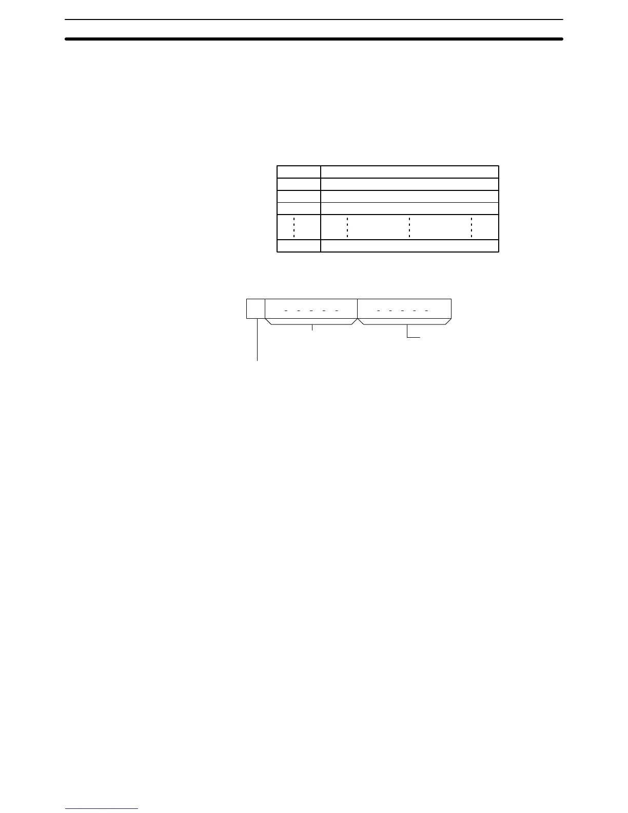
The following diagram shows the function of words D to D+N+1.
D Average
value (after N or more cycles)
D+1
Previous value pointer and cycle indicator
D+2
Previous value #1
D+3
Previous value #2
D+N+1
Previous value #N
The
function of bits in D+1 are shown in the following diagram and explained in
more detail below.
15 14 08 07 00
Previous
value pointer
(2-digit hexadecimal from 0 to N–1.)
D+1:
Not used. Set to zero.
Cycle indicator
0 (OFF): cycles since execution of AVG(––) < N.
1 (ON): cycles since execution of AVG(––) N.
Previous Value Pointer The
previous value pointer indicates the location where the most
recent value of
S
was stored relative to D+2, i.e., a pointer value of 0 indicates D+2, a value of 1
indicates D+3, etc.
Cycle Indicator The
cycle indicator is turned ON after A
VG(––) has
been executed N times. At
this
point, D will contain the average value of the contents of
words D+2 through
D+N+1.
The average value is 4-digit hexadecimal and is rounded of
f to the near
-
est integer value.
Flags ER: Indirectly
addressed
DM word is non-existent. (Content of
:
DM word is
not BCD, or the DM area boundary has been exceeded.)
One or more operands have been set incorrectly.
Special Math Instructions Section 5-21

Table of Contents

Other manuals for Omron SYSMAC C200HS

Questions and Answers:

Omron SYSMAC C200HS Specifications

General IconGeneral
ModelC200HS
ManufacturerOmron
SeriesSYSMAC
Humidity10 to 90% RH (non-condensing)
Programming LanguageLadder logic
Program MemoryRAM/EPROM/EEPROM
Communication ProtocolsSYSMAC LINK, SYSMAC NET
Communication PortsRS-232C, RS-422
Power Supply100-240V AC, 24V DC
Operating Temperature0 to 55°C
Vibration Resistance10 to 57 Hz, 0.075mm amplitude

Summary

SECTION 1 Introduction

1-1 Overview

Provides a general introduction to Programmable Controllers (PCs), their operation, and programming concepts.

SECTION 2 Hardware Considerations

2-1 CPU Components

Details the main components of the C200HS CPU, including indicators, fuses, and connection ports.

SECTION 3 Memory Areas

SECTION 4 Writing and Inputting the Program

4-4 Basic Ladder Diagrams

Introduces fundamental concepts of ladder diagram programming, including rungs, conditions, and instructions.

4-7 Inputting, Modifying, and Checking the Program

Details the procedures for entering, editing, checking, and debugging programs using the Programming Console.

SECTION 5 Instruction Set

5-8 Ladder Diagram Instructions

Details fundamental instructions used in ladder diagrams like LOAD, AND, OR, and their variations.

SECTION 6 Program Execution Timing

6-4 I/O Response Time

Details the time taken for the PC to respond to input signals and produce output signals.

SECTION 7 Program Monitoring and Execution

7-1 Monitoring Operation and Modifying Data

Covers procedures for observing and modifying PC data like bits, words, timers, and counters.

SECTION 8 Communications

8-2 Parameters for Host Link and RS-232C Communications

Details essential PC Setup parameters required for enabling Host Link and RS-232C communications.

SECTION 10 Troubleshooting

10-4 Error Messages

Lists common error messages, their probable causes, and possible corrections for diagnosing system problems.

SECTION 11 Host Link Commands

11-3 Host Link Commands

Details the various commands used for host computer communication with the C200HS PC.

Appendix B Programming Instructions

Appendix D Memory Areas

Appendix E PC Setup

RS-232C Port Settings (DM 6645 to DM 6649)

Details the specific parameters for configuring the RS-232C port, essential for communication setup.

Related product manuals