EasyManua.ls Logo

Omron SYSMAC C200HS User Manual

Omron SYSMAC C200HS
503 pages
To Next Page IconTo Next Page
To Previous Page IconTo Previous Page
Page #268 background imageLoading...
Page #268 background image
258
Description A subroutine can be executed by placing SBS(91) in the main program at the
point
where the subroutine is desired. The subroutine number used in SBS(91)
indicates
the desired subroutine. When
SBS(91) is executed (i.e., when the ex
-
ecution condition for it is ON), the instructions between the SBN(92) with the
same
subroutine number and the first RET(93) after it are executed before
ex
-
ecution returns to the instruction following the SBS(91) that made the call.
SBS(91) 00
SBN(92) 00
RET(93)
END(01)
Main program
Subroutine
Main program
SBS(91)
may be used
as many times as desired in the program, i.e., the same
subroutine may be called from different places in the program).
SBS(91)
may also be placed into a subroutine to shift program execution from
one subroutine to another, i.e., subroutines may be nested. When the second
subroutine
has been completed (i.e., RET(93) has been reached), program ex
-
ecution
returns to the original subroutine which is then
completed before return
-
ing
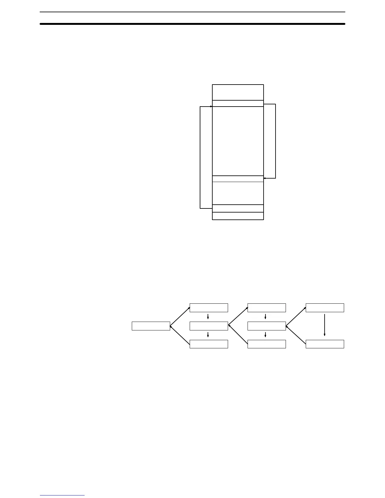
to the main program. Nesting is possible to up to sixteen levels. A subroutine
cannot call itself (e.g., SBS(91) 00 cannot be programmed within
the
subroutine
defined
with SBN(92) 00). The following diagram illustrates two levels of nesting.
SBN(92)
10
SBN(92) 1
1
SBN(92) 12
SBS(91) 1
1
RET(93)
SBS(91) 10 SBS(91) 12
RET(93) RET(93)
Subroutines and Interrupt Control Section 5-23

Table of Contents

Other manuals for Omron SYSMAC C200HS

Questions and Answers:

Omron SYSMAC C200HS Specifications

General IconGeneral
ModelC200HS
ManufacturerOmron
SeriesSYSMAC
Humidity10 to 90% RH (non-condensing)
Programming LanguageLadder logic
Program MemoryRAM/EPROM/EEPROM
Communication ProtocolsSYSMAC LINK, SYSMAC NET
Communication PortsRS-232C, RS-422
Power Supply100-240V AC, 24V DC
Operating Temperature0 to 55°C
Vibration Resistance10 to 57 Hz, 0.075mm amplitude

Summary

SECTION 1 Introduction

1-1 Overview

Provides a general introduction to Programmable Controllers (PCs), their operation, and programming concepts.

SECTION 2 Hardware Considerations

2-1 CPU Components

Details the main components of the C200HS CPU, including indicators, fuses, and connection ports.

SECTION 3 Memory Areas

SECTION 4 Writing and Inputting the Program

4-4 Basic Ladder Diagrams

Introduces fundamental concepts of ladder diagram programming, including rungs, conditions, and instructions.

4-7 Inputting, Modifying, and Checking the Program

Details the procedures for entering, editing, checking, and debugging programs using the Programming Console.

SECTION 5 Instruction Set

5-8 Ladder Diagram Instructions

Details fundamental instructions used in ladder diagrams like LOAD, AND, OR, and their variations.

SECTION 6 Program Execution Timing

6-4 I/O Response Time

Details the time taken for the PC to respond to input signals and produce output signals.

SECTION 7 Program Monitoring and Execution

7-1 Monitoring Operation and Modifying Data

Covers procedures for observing and modifying PC data like bits, words, timers, and counters.

SECTION 8 Communications

8-2 Parameters for Host Link and RS-232C Communications

Details essential PC Setup parameters required for enabling Host Link and RS-232C communications.

SECTION 10 Troubleshooting

10-4 Error Messages

Lists common error messages, their probable causes, and possible corrections for diagnosing system problems.

SECTION 11 Host Link Commands

11-3 Host Link Commands

Details the various commands used for host computer communication with the C200HS PC.

Appendix B Programming Instructions

Appendix D Memory Areas

Appendix E PC Setup

RS-232C Port Settings (DM 6645 to DM 6649)

Details the specific parameters for configuring the RS-232C port, essential for communication setup.

Related product manuals