305
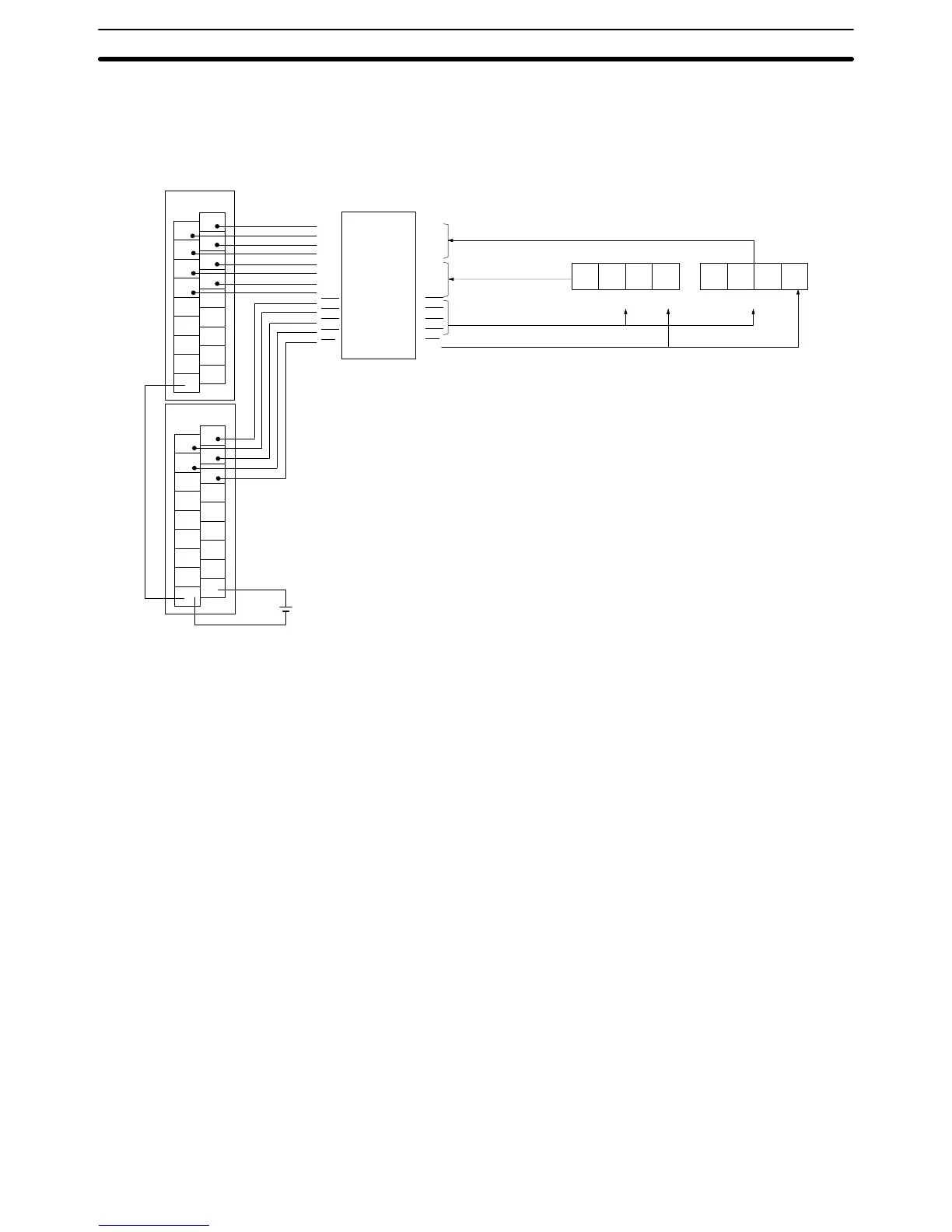
Hardware With this instruction, 8-digit BCD set values are read from a digital switch.
DSW(––)
utilizes 5 output bits and 8 input bits. Connect the digital switch and the
Input and Output Units as shown in the diagram below. Output point 5 will be
turned
ON when one round of data is read, but there is no need to connect output
point 5 unless required for the application.
1
3
5
7
9
11
13
15
COM
0
2
4
6
8
10
12
14
COM
ID212
1
3
5
7
9
11
13
15
COM
0
2
4
6
8
10
12
14
COM
OD212
D
0
D
1
D
2
D
3
D
0
D
1
D
2
D
3
CS
0
CS
1
CS
2
CS
3
RD
D
0
D
1
D
2
D
3
D
0
D
1
D
2
D
3
CS
0
CS
1
CS
2
CS
3
RD
Interface
A7E
data line
leftmost digits
T
o A7E chip selection
T
o A7E RD terminal
Leftmost digits
A7E
Rightmost digits
A7E data line rightmost digits
Input Unit
Output Unit
Note
An interface to convert
signals
from 5 V to 24 V is
required to connect an A7E digital switch.
Advanced I/O Instructions Section 5-28