420
Parameters Status Data, Message (Response)
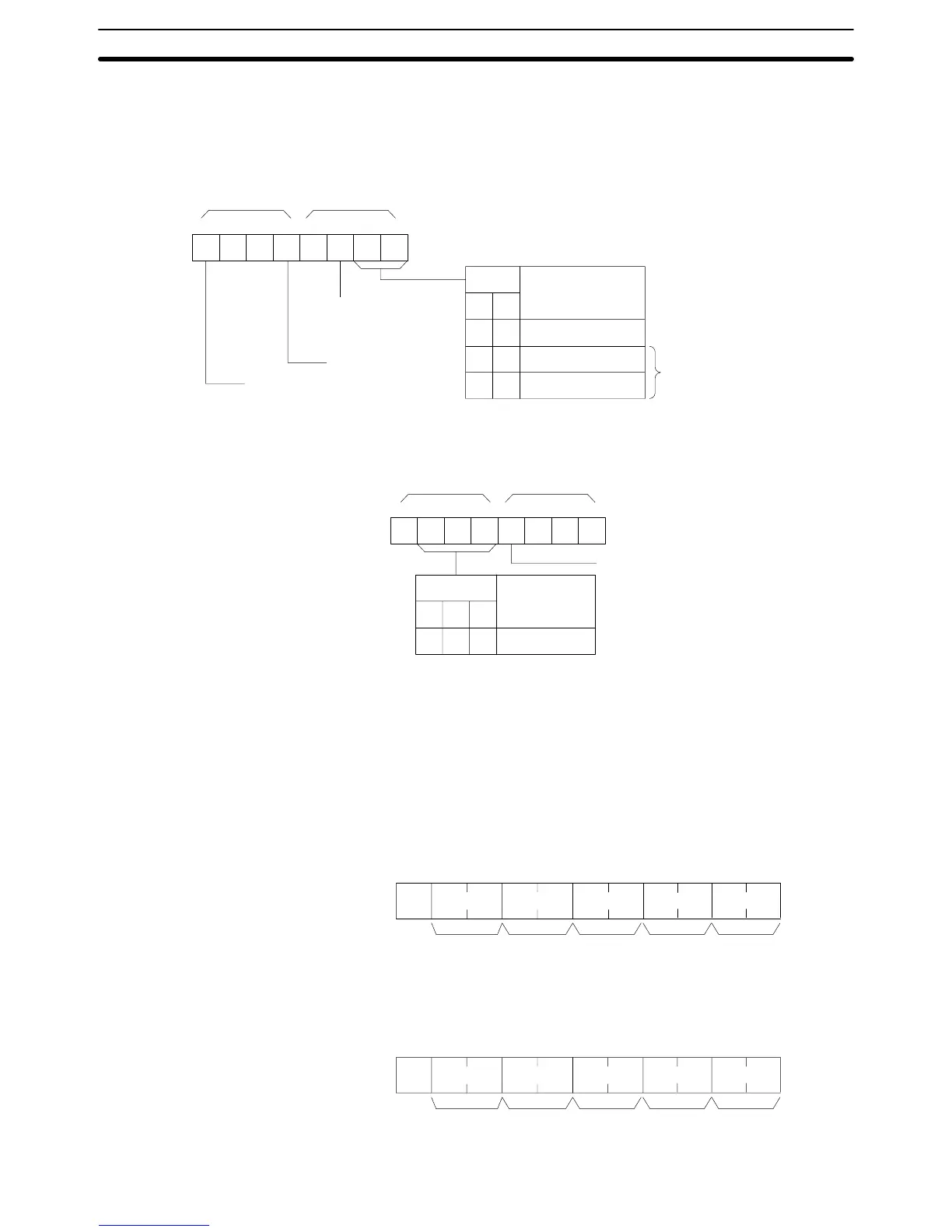
“Status
data” consists of four digits (two bytes) hexadecimal. The leftmost byte
indicates
CPU operation mode, and the rightmost byte indicates the size of
the
program area.
15
14 13 12 11 10 9 8
00 0
98
00
10
1
1
x
16
3
x 16
2
This area is dif
ferent
from that of
STATUS WRITE.
Bit
Bit
1: F
ALS generated
1:
Fatal error generated
Operation
mode
PROGRAM
mode
RUN mode
MONITOR
mode
1: Remote I/O
waiting for power
application
76543210
1 000
x
16
1
x 16
0
65
10
4
0
Bit
Bit
32
Kbytes
Program
area write enable
0: Disabled (DIP switch pin 1 is ON)
1: Enabled (DIP switch pin 1 is OFF)
Program area
“Message” indicates the FAL/FALS number generated at the point when the
command is executed. When there is no message, this is omitted.
11-3-22 STATUS WRITE –– SC
Changes the PC operating mode.
Command Format
@ SC
x
10
0
x 10
1
x 16
1
x 16
0
↵
:
Node no.
Header
code
TerminatorFCS
Mode data
Response Format
@ SC
x
10
0
x 10
1
x 16
1
x 16
0
: ↵
TerminatorFCS
Node no.
Header
code
End code
Host Link Commands
Section 11-3