Call Out Description
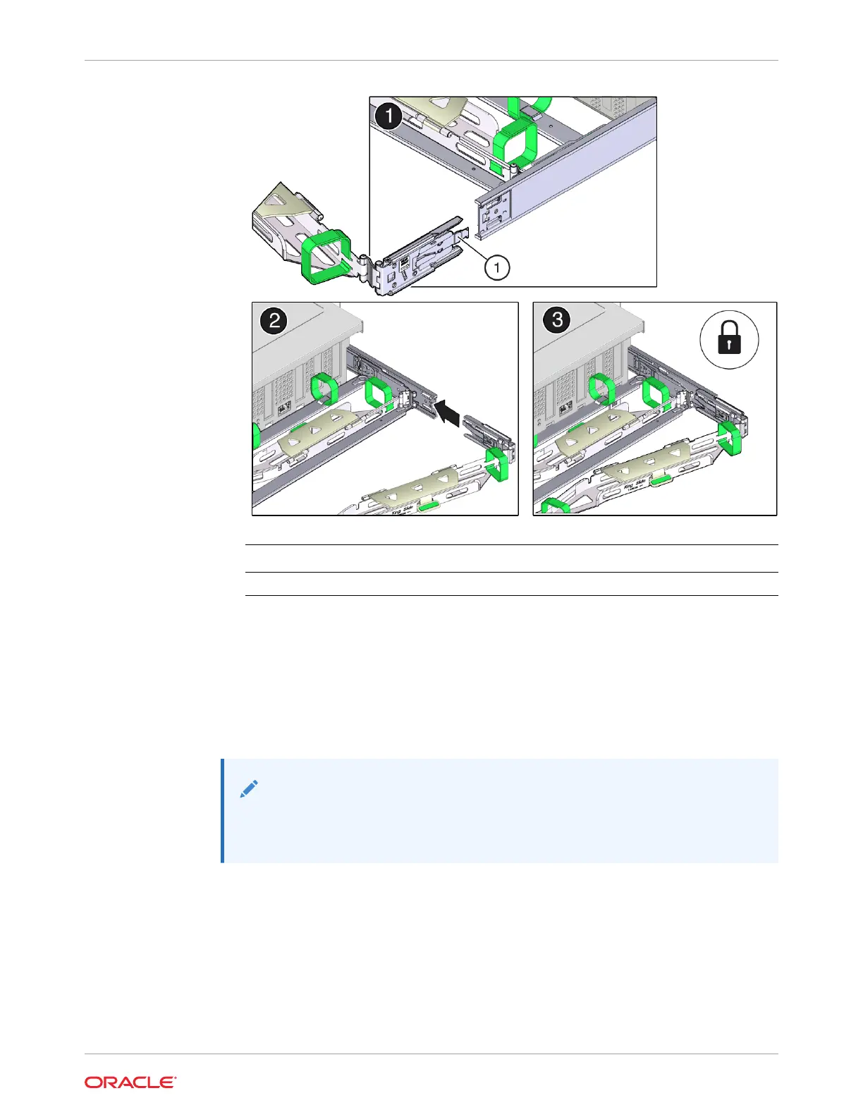
1 Connector C locking spring
b. Insert connector C into the right slide-rail until it locks into place with an audible click
[2 and 3].
c. Gently tug on the right side of the CMA back slide bar to verify that connector C is
properly seated.
6. To prepare CMA connector D for installation, remove the tape that secures the slide-rail
latching bracket to connector D, and ensure that the latching bracket is properly aligned
with connector D [1 and 2].
Note:
The CMA is shipped with the slide-rail latching bracket taped to connector D.
You must remove the tape before you install this connector.
Chapter 6
Install the Cable Management Arm (Optional)
6-9