Call
Out
Description
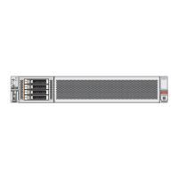
1 Connector D release tab (green)
2 Slide-rail latching bracket release tab (labeled PUSH)
b. Use your right hand to support the CMA and use your left thumb to push in
(toward the left) on the slide-rail latching bracket release tab labeled PUSH
(callout 2), and pull the latching bracket out of the left slide-rail and put it aside
[3 and 4].
5. To disconnect connector C:
a. Place your left arm under the CMA to support it.
b. Use your right thumb to push in (toward the right) on the connector C release
tab labeled PUSH (callout 1), and pull connector C out of the right slide-rail [1
and 2].
Call Out Description
1 Connector C release tab (labeled PUSH)
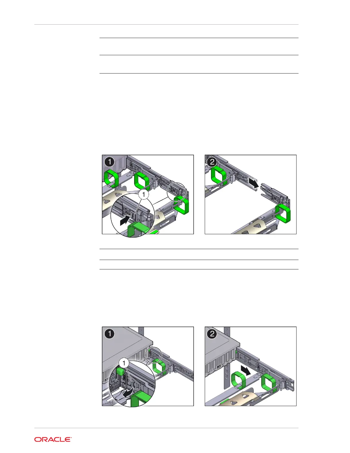
6. To disconnect connector B:
a. Place your right arm under the CMA to support it and grasp the back end of
connector B with your right hand.
b. Use your left thumb to pull the connector B release lever to the left, away from
the right slide-rail (callout 1), and use your right hand to pull the connector out
of the slide-rail [1 and 2].
Chapter 2
Preparing the Server for Component Replacement
2-16