– 145 –
Chapter 9 External Interfaces — GPI input/output settings and alarm output
GPI input/output settings and alarm output
The unit has 18 GPI input ports in the <GPI IN> terminal of Main Frame AV-HS60U1/AV-HS60U2 and 8 in the <GPI I/O> terminal of Control Panel
AV-HS60C1/AV-HS60C2.
It also has 48 GPI output ports in the <GPI OUT1>/<GPI OUT2> terminal of Main Frame AV-HS60U1/AV-HS60U2 and 10 in the <GPI I/O> terminal of
Control Panel AV-HS60C1/AV-HS60C2.
Assign functions to the ports through the <SYS> button on the top menu → [PERIPHERAL] → [GPI IN]/[GPI OUT] tab.
For details, refer to “System Menu” (page 125).
Also, alarm signals can be output externally from specic pins of the <GPI IN> terminal (Main Frame AV‑HS60U1/AV‑HS60U2) and <GPI I/O> terminal
(Control Panel AV-HS60C1/AV-HS60C2).
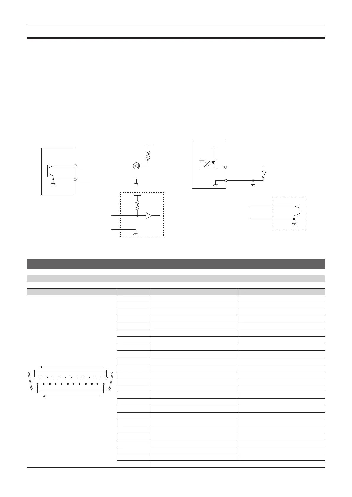
r Connection examples
GPI OUT, alarm connection examples (Fig. 1): Make sure that the following conditions are satised.
Dielectric strength: Max. DC 24 V
Current: Max. 50 mA
GPI IN connection example (Fig. 2): Provide contact inputs.
Open collector output
Fig. 1 Fig. 2
Open collector output
GND
Logic
GND
+3.3 V
(Max. voltage: 24 V)
Tally, alarm LED
AV-HS6000
AV-HS6000
GPI input/output ports of the Main Frame AV‑HS60U1/AV‑HS60U2
Pin assignments and signal names of the <GPI OUT1>/<GPI OUT2> terminal
Outside view Pin No. Signal Name (<GPI OUT1> terminal) Signal Name (<GPI OUT2> terminal)
1
1425
13
1 GPI OUT-1 GPI OUT-25
2 GPI OUT-2 GPI OUT-26
3 GPI OUT-3 GPI OUT-27
4 GPI OUT-4 GPI OUT-28
5 GPI OUT-5 GPI OUT-29
6 GPI OUT-6 GPI OUT-30
7 GPI OUT-7 GPI OUT-31
8 GPI OUT-8 GPI OUT-32
9 GPI OUT-9 GPI OUT-33
10 GPI OUT-10 GPI OUT-34
11 GPI OUT-11 GPI OUT-35
12 GPI OUT-12 GPI OUT-36
13 GPI OUT-13 GPI OUT-37
14 GPI OUT-14 GPI OUT-38
15 GPI OUT-15 GPI OUT-39
16 GPI OUT-16 GPI OUT-40
17 GPI OUT-17 GPI OUT-41
18 GPI OUT-18 GPI OUT-42
19 GPI OUT-19 GPI OUT-43
20 GPI OUT-20 GPI OUT-44
21 GPI OUT-21 GPI OUT-45
22 GPI OUT-22 GPI OUT-46
23 GPI OUT-23 GPI OUT-47
24 GPI OUT-24 GPI OUT-48
25 COM (GND)