17-00001-C Page | 52
Step 3: Non-conductive mode (continued)
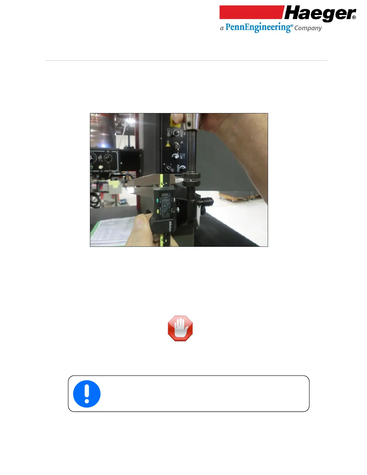
5. Carefully grasp the sides of the Upper Tool Holder and raise it until a positive stop position is
reached. With a calibrated measuring instrument (Digital calipers are best), measure the
vertical distance between the upper and lower Anvils. If this measurement is at least a
minimum of .060” in. /1.52 mm, go to Instruction 5.
a. If this dimension is less than.060” in. /1.52 mm, the Safety System has failed!
Immediately turn the machine off by pressing the red Off Switch and turning the Main
Disconnect Switch to the Off position. The machine’s Main Disconnect Switch must be
locked in the Off position until repairs are begun and follow Lock-out/Tag-out procedures.
Do not operate this machine until qualified personnel have repaired the machine and the
Non-Conductive Mode has been properly tested.
6. Next keep your hands away from the tooling area. Depress the Down Foot pedal switch a second
time. The machine should exert the pre-set 3,000 lb/13 Kn force to both upper and lower Anvils and
then return to its Up position.
If this machine completes the above sequence correctly, the test of
the Safety Switch and Safety System is complete and operating
properly.