Description of the AXC 3050 controller
8686_en_01 PHOENIX CONTACT 19
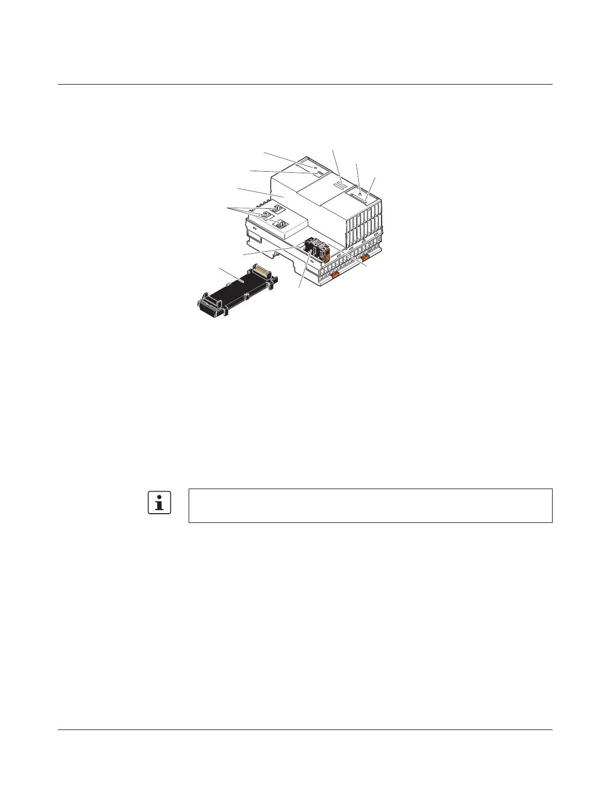
2.4 Connection and operating elements
Figure 2-6 Structure of the controller
The controller for Axioline consists of the following components:
1 Bus base module
2 Reset buttons
3 PROG (X4) service and programming interface
4 Electronics module
5 Ethernet interfaces (X1, X2, X3)
6 FE tab (X5); 2.8 mm for optional connection to functional earth ground
7 Connector for connecting the supply voltage
8 USB interface (X6)
9 Slot for the parameterization memory/card holder (SD card)
10 Mode selector switch
11 Diagnostics and status indicators
The SD card is not supplied as standard with the controller.
Please refer to the ordering data in Section “Accessories” on page 132.
 Loading...


