AXC 3050
30
PHOENIX CONTACT 8686_en_01
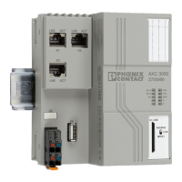
2.10.1.1 Ethernet
Three standardized Ethernet interfaces(X1/X2/X3) are available at the AXC 3050 controller
for connecting the Ethernet network.
The Ethernet network is connected via RJ45 sockets.
The contact assignment of the interface is as follows:
Figure 2-13 Ethernet interface and pin assignment
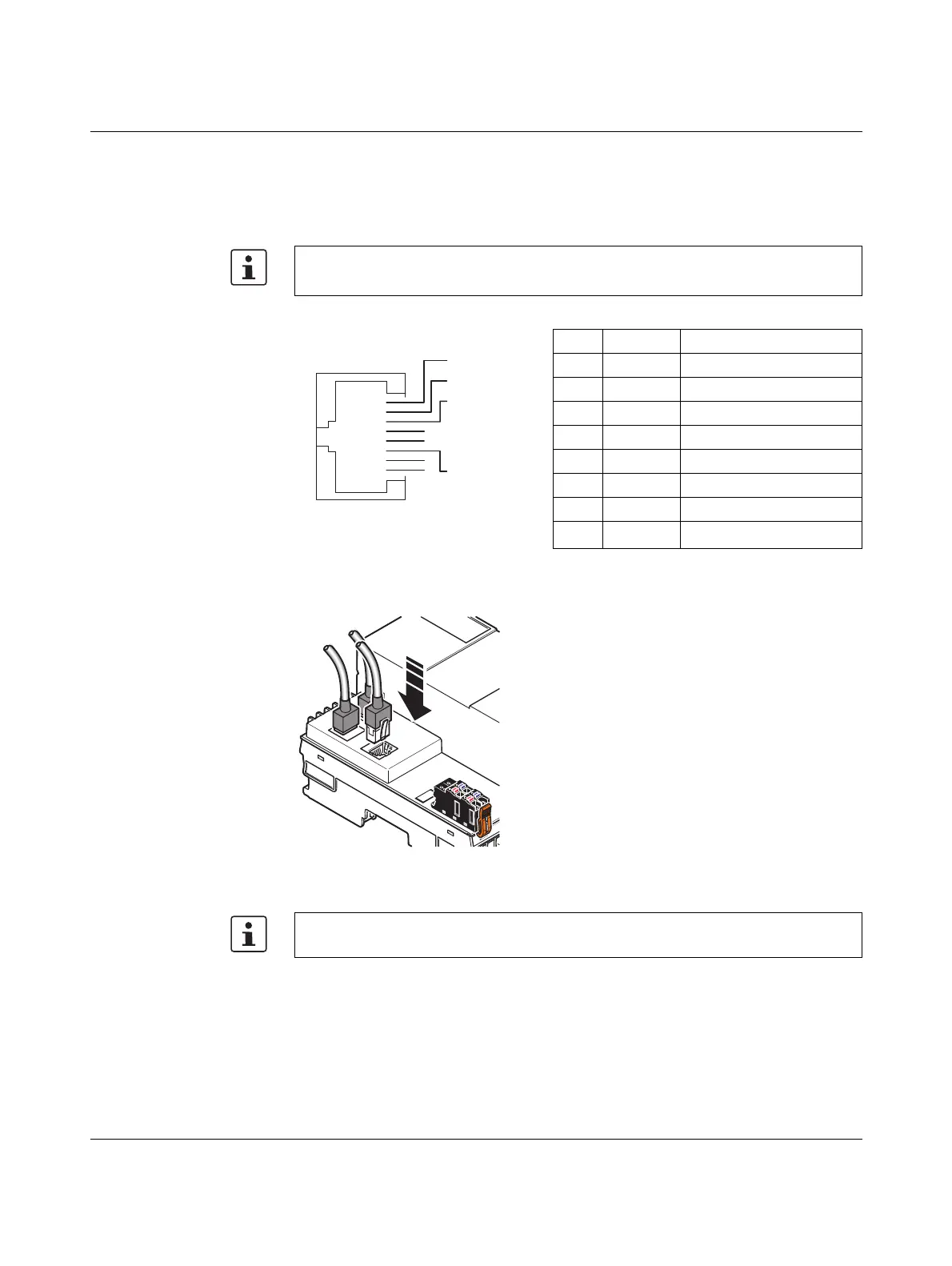
Figure 2-14 Connecting the Ethernet cable to the controller
Use an Ethernet cable according at least to CAT5 of IEEE 802.3.
Observe the bending radii of the Ethernet cables used.
Pin Signal Meaning
1T+ Transmit data +
2T- Transmit data -
3 R+ Receive data +
4– –
5– –
6 R- Receive data -
7– –
8– –
The Ethernet interface is able to switch over the transmitter and receiver automatically
(auto crossover).
RJ45
Pin 1
Pin 2
Pin 3
Pin 4
Pin 5
Pin 6
Pin 7
Pin 8
 Loading...


