AXC 3050
14
PHOENIX CONTACT 8686_en_01
Protection against voltage
failure
The device firmware detects voltage failure of the AXC 3050. An automatic backup is per-
formed of the retain data (system variables of the controller, which are marked in the
PC Worx project as “remanent”) on the active parameterization memory (internal or SD
card). A task intended by the application programmer to protect the system, e.g., for data
backup, can also be started. To this end, an event task can be defined for the “voltage fail-
ure” event as an option (see Section 4.12, “Event task for the voltage failure event”). A max-
imum of 50 ms are available to perform the event task.
The state of the voltage failsafe can be queried using system variables (see Section 6.10,
“Power supplies”).
Data buffering following
voltage failures
In the event of voltage failure, the AXC 3050 saves the most important control data (retain
data) on the inserted parameterization memory.
Reverse polarity protec-
tion
The power supply inputs are protected against polarity reversal.
Realtime clock In the event that the supply voltage fails, the realtime clock integrated in the AXC 3050 is
buffered (see Section “Technical data” on page 127). Its state can be queried using system
variables (see Section “Power storage, realtime clock” on page 118).
2.2 Possible fields of application of the AXC 3050
2.2.1 The AXC 3050 as a distributed controller of an Axioline F
station
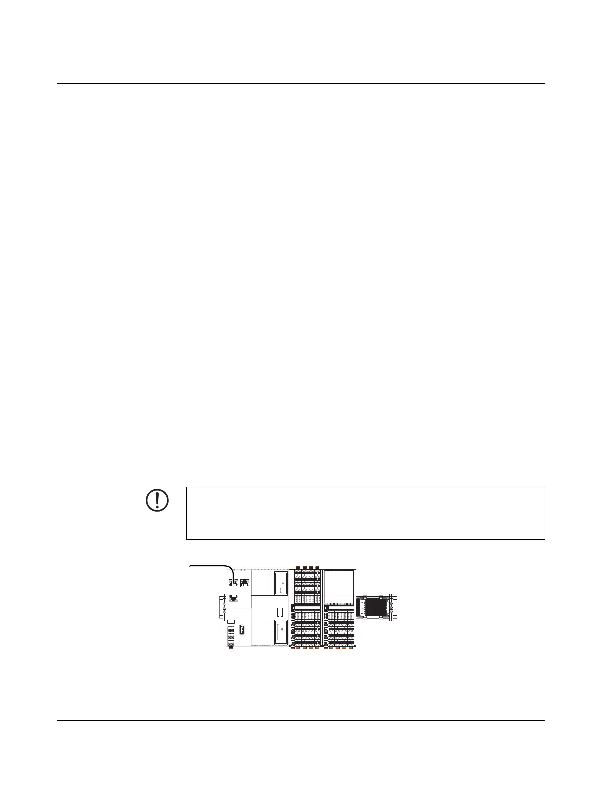
The AXC 3050 can be used as a distributed controller of an Axioline F station which is con-
nected to an Ethernet system. A maximum of 63 devices (Axioline F modules) can be con-
nected to the controller. The maximum number of devices that can be connected depends
on the current consumption of the devices. The total current consumption of all devices ar-
ranged on the controller must not exceed the maximum current that the controller supplies
for the local bus.
Figure 2-2 Axioline F station with AXC 3050 controller
NOTE: Electronics may be damaged when overloaded
Observe the current consumption of each device when configuring an Axioline F station.
It is stipulated in every module-specific data sheet and may vary. As such, the permissible
number of devices that can be connected therefore depends on the station structure.
D
UI
E1
E2
a2
b1
b2
a1
16
06
26
36
07
17
27
37
04
24
14
34
05
15
25
35
32
22
12
02 03
13
23
33
00
10
20
30
01
11
21
31
D
UA
E1
E2
a2
b1
b2
a1
16
06
26
36
07
17
27
37
04
24
14
34
05
15
25
3532
22
12
02 03
13
23
33
00
10
20
30
01
11
21
31
56
46
66
76
47
57
67
77
44
64
54
74
45
55
65
7572
62
52
42 43
53
63
73
40
50
60
70
41
51
61
71
8686A002
Ethernet
 Loading...


