Mounting/removal and power supply
8686_en_01 PHOENIX CONTACT 39
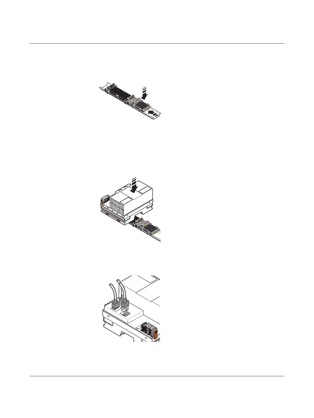
• Push each subsequent bus base module into the connection of the previous bus base
module (B).
Figure 3-3 Mounting bus base modules
Snapping on the controller • Place the controller vertically on the first bus base module and the DIN rail until it snaps
into place with a click.
• Make sure that the device plug for the bus base connection is situated above the cor-
responding socket on the bus base module.
Figure 3-4 Snapping on the controller
Connecting Ethernet • Connect the Ethernet network to the RJ45 sockets.
Figure 3-5 Connecting Ethernet
 Loading...


