Cleaning, checks and maintenance
Operating Manual PSEN sc M 3.0/5.5 08-17
1005387-EN-05
| 118
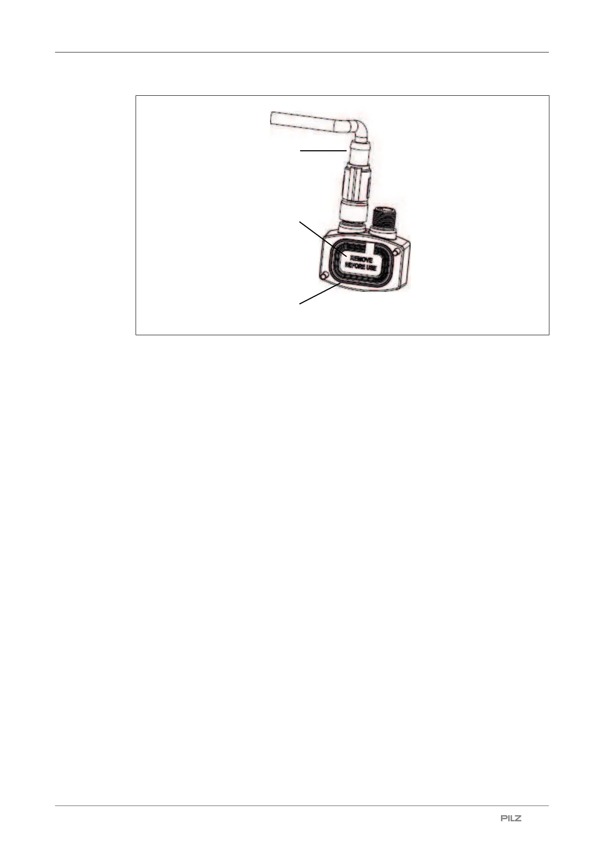
Legend
[1] Protective membrane
[2] Memory module
[3] Cable with connector
7. Screw the memory module with 1 Nm.
8. Place the protective cover at the safety laser scanner and screw the protective covers
with 1 Nm.
9. Switch the safety laser scanner on.
The system checks whether the conditions are met. When the conditions are met,
restoring of the configuration is started.
10. Depending on the type of difference between memory module and PSEN sc M 3.0/5.5
08-17 series the restoring of the configuration varies.
Serial numbers differ: On the display of the master unit, CFG NO MATCHING is shown.
Continue by selecting the data for the restoring.
Topology or MIB files vary: On the display of the master unit WAITING CONF is shown.
Continue the configuration in PSENscan Configurator.
11. Use the buttons on the display of the master unit to select the data to be used for
restoring.
Display master unit:
Restore cfg: The configuration in the memory module is used. Confirm the selection
with Confirm and the configuration is copied from the memory module to the PSEN sc
M 3.0/5.5 08-17 series. Continue checking the configuration.
cfg from GUI: The new configuration created in the PSENscan Configurator is used.
Confirm your selection with Confirm and continue with Create new configuration in
PSENscan Configurator.

 Loading...

