Project configuration
Operating Manual PSEN sc M 3.0/5.5 08-17
1005387-EN-05
| 57
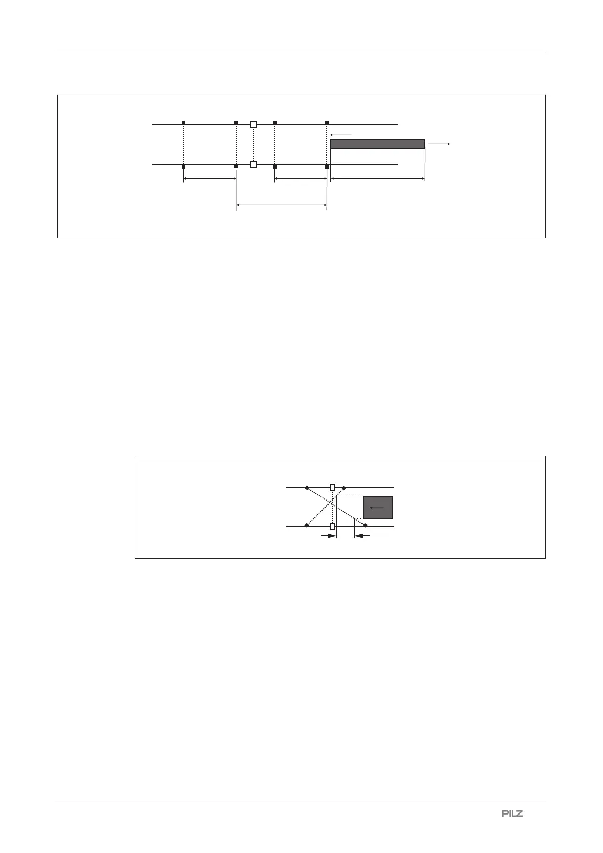
L
A1B1
[1]
A2
B2
D
A-B
V
D
MutingOff
D
A-B
Fig.: Distances between muting sensors - 4 muting sensors
Legend
[1] Safety laser scanner
A1 First muting sensor on the input side, connected to Muting 11
B1 Second muting sensor on the input side, connected to Muting 12
A2 First muting sensor on the output side, connected to Muting 11
B2 Second muting sensor on the output side, connected to Muting 12
L Length of the object that triggers the muting state as it passes the muting
sensors
V Speed at which the object is moving
D
A-B
Distance between the muting sensors A1 and B1, and between A2 and B2
D
MutingOff
Distance between muting sensor A1 and muting sensor A2
Fig.: Distances between muting sensors - Cross muting
Legend
[1] Safety laser scanner
A1 First muting sensor on the input side, connected to Muting 11
B1 Second muting sensor on the input side, connected to Muting 12
d2 Distance that the object covers from the first muting sensor A1 to the second mut-
ing sensor B2 in max. 4 s
V Speed at which the object is moving

 Loading...

