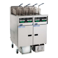
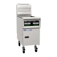
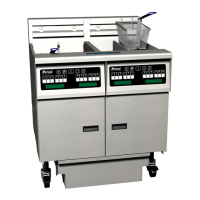
Pitco SSHLV (ROV) Gas Fryers
3.3 Thermostats
SSHLV Series gas fryers have temperature probes located above and between the third and fourth
heat tube of each fryvat (split vat fryers have two probes, one in each vat). SSHLV fryers, like all
Solstice series fryers, use a thermistor style temperature probe. In this type of thermostat, the probe
resistance varies directly with the temperature. That is, as the temperature rises, so does resistance.
Circuitry in the controller monitors the probe resistance and controls burner firing when the resistance
exceeds or falls below programmed temperatures (setpoints). SSHLV Series gas fryers are also
equipped with a high-limit thermostat. In the event that the fryer fails to properly control the oil
temperature, the high-limit thermostat prevents the fryer from overheating to the flash point. The high-
limit thermostat acts as a normally closed power switch that opens when exposed to temperatures
above 425°F to 450°F (218°C to 232°C).
3.4 Fryer Sequence Operation
The SSHLV fryer components function in specific order of operation. Knowing and understanding the
sequence of fryer and components operation enables you to diagnose equipment failure more
accurately.
3.5 Heating System
The unit is connected to line voltage:
• If Fuse F1 on the relay board is good:
• The A.C. indicator is illuminated.
• The controller is supplied with 24 VAC.
• With the drain valve handle closed, the proximity switch supplies 24 VAC to the drain valve
interlock (DVI) input at the controller.
• 24 VAC is at the Side On (SO). relay COM contact.
• The controller is turned ON:
• The SO indicator on the relay board is illuminated.
• The SO relay is energized, closing the circuit.
• With the roll out switch and hi-limit in the closed position, the ignition module receives 24VAC
at terminal 6 (24 VAC).
• The ignition module:
• Sends 24 VAC from terminal 3(PV) to the PV terminal on the gas valve.
• Sends the igniter 15kv to spark.
• Senses the flame once the pilot has lit and it sends 24 VAC at terminal 1(MV) and puts 24 VAC
at the Heat Demand (HD) relay COM contact on the relay board. The HD relay on the relay board
interrupts the 24 VAC supply to the gas valve until the controller calls for heat.
When the controller is on, the pilot should always remain lit.
• The controller calls for heat:
• The HD indicator on the relay board is illuminated.
L22-392 R1 14