CLUTCHING
4.22
Disassembly and Inspection
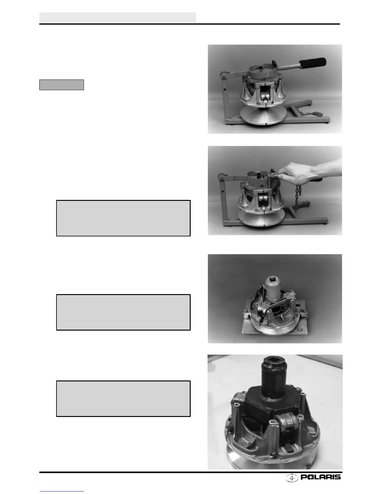
1. Install drive clutch in clutch compression tool
(8700220). Mark both moveable and fixed sheave,
cover, and spider with a permanent marker.
CAUTION:
Sheaves must be marked to provide a reference point for
clutch balance and spider indexing. If the sheaves are
not marked, and spider shim washers are changed or
misplaced, the clutch will be out of balance and must be
replaced. See page 4.28 for indexing procedure.
2. Carefully and evenly remove cover attaching bolts.
Do not allow side loading or misalignment of cover or
bushing may be damaged. Remember there is
spring tension on the cover. Inspect cover bushing
for wear. See page NO TAG for inspection and repair
procedure.
3. Mount drive clutch securely in the holding fixture. On
models equipped with a spider jam nut (P-85
Clutches), remove jam nut in a counterclockwise
direction (standard thread) using the special tool.
4. Install spider removal tool and remove spider in a
counterclockwise direction (standard thread).
Drive Clutch Holding Fixture
PN 2871358
Drive Clutch Compression Tool
PN 8700220
Spider Spanner (Jam Nut) Tool
PN 2870338
Spider Removal Tool
PN 2872987
Enfocus Software - Customer Support
 Loading...