ELECTRICAL
8.7
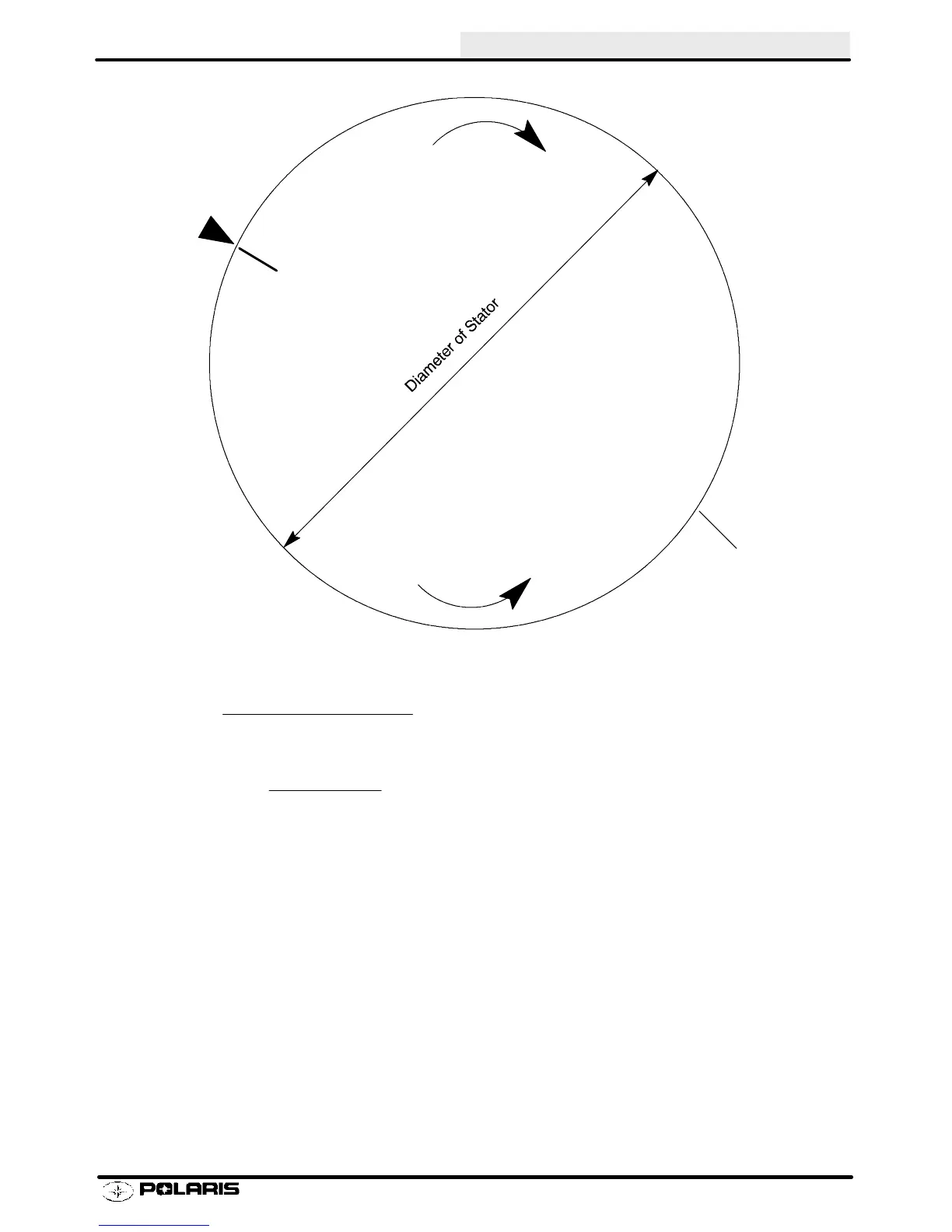
Stator Diameter
Ignition System Testing
Ignition system components can be individually tested by measuring their internal resistance and insulation to
ground. These checks must be done with a digital volt/ohm meter. Compare the readings obtained to the values
listed on the chart. Actual values may vary up to á 10% between like components. Any readings outside the span
should be considered questionable.
NOTE: The stator coils can be checked without removing them from the engine. Simply disconnect the connector
plug in the stator-to-CDI wire and check the resistance values between the wire colors. Consult the stator
schematics shown at the end of this section.
For specific information, consult the wiring diagrams at the end of this section.
NOTE: Secondary coils can also be dynamically tested with a coil power tester. Consult the tester operation
manual for specific operating instructions.
Stator Plate
Retard
Advance
Stator Mark
Crankcase
Mark
The formula for determining stator movement per degree of timing:
Diameter of stator x 3.1416
360q
= thousandths of stator movement
per degree of timing
Example:
4.000 x 3.1416
360q
= .035s of stator movement per one degree of stator movement
Enfocus Software - Customer Support
 Loading...