ELECTRICAL
8.6
CDI Ignition Timing
Timing Procedure - All Models
NOTE: Always verify timing of engine at room temperature only (68q F/20q C, no engine warm up) and at the
proper RPM.
1. Refer to the timing specification charts at the beginning of this section to determine the proper ignition timing
for the engine you are working on.
2. Use a dial indicator to place the piston in the proper timing position and mark the flywheel at this point.
3. Connect an accurate tachometer and a good quality timing light to the engine according to manufacturer’s
instructions.
Disconnect the TPS (Throttle Position Sensor) connector from carburetor.
4. Start engine and increase RPM to the point
specified in the timing specifications in Chapter 1.
Hold the throttle to maintain specified timing
RPM.
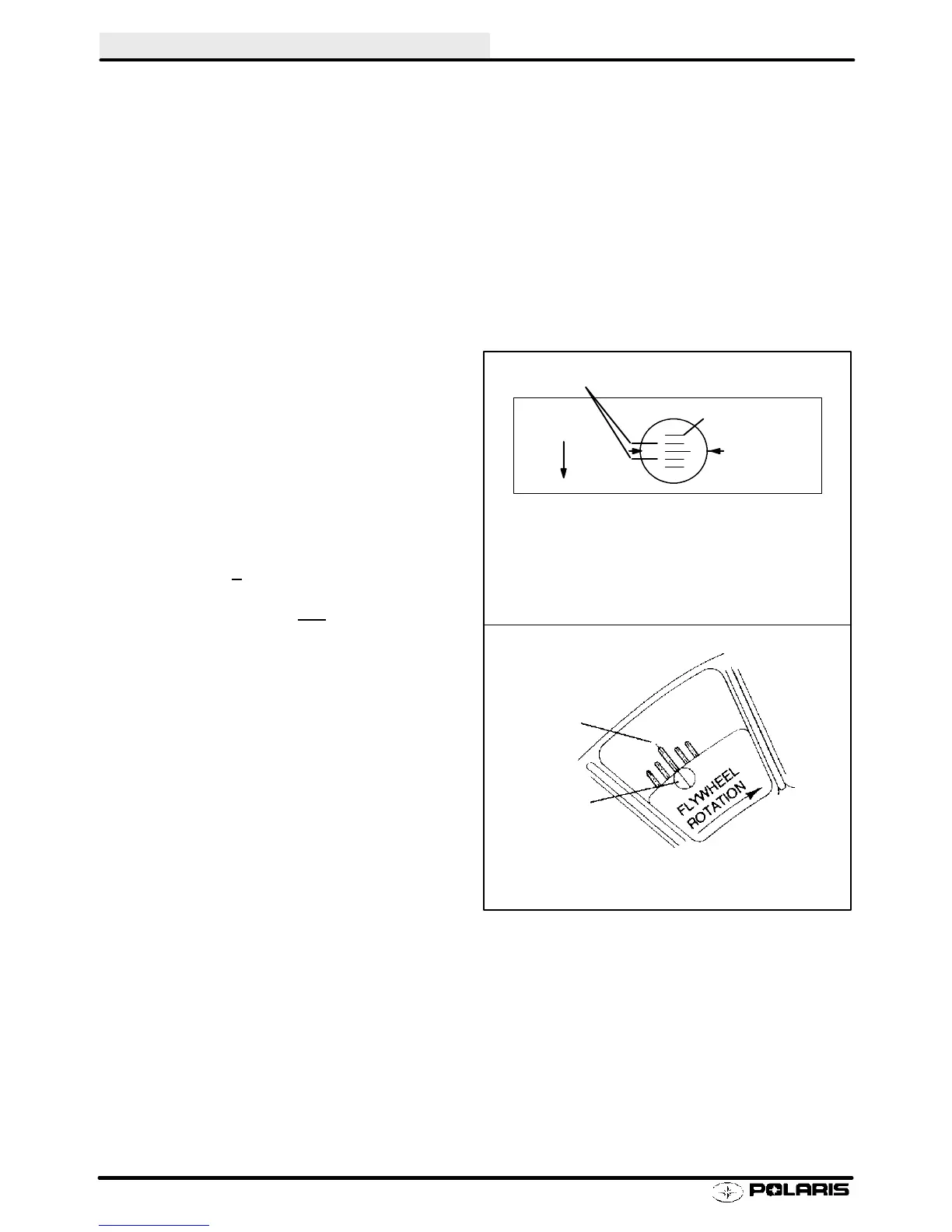
5. Point the timing light at the timing inspection hole.
6. With your head positioned so there is a straight
line between your eye, the stationary pointer and
the crankshaft center line, note the relative
position between the marked flywheel line and the
stationary pointer. If the stationary pointer is
aligned with the mark made in Step 2, (or within
the acceptable +
variance) the timing is correct.
7. If the pointer is outside the variance, the stator will
have to be rotated either with
crankshaft rotation
(to retard the timing) or
against
rotation to
advance it.
NOTE: Rotate stator plate approximately the same
distance as the marks must move.
NOTE: In most cases, the recoil starter housing, re-
coil drive hub, and flywheel must be removed to loos-
en the stator bolts and change the timing. On some
engines, the stator plate retaining screws can be ac-
cessed through the flywheel.
8. Torque stator plate screws and flywheel nut to
specified torque. Apply Loctite 262 (red) to
crankshaft flywheel taper if required. Refer to the
Specifications section for torque specifications
and flywheel installation procedure for engine
type.
Flywheel
Rotation
Acceptable Variance
Flywheel Lines
Stationary
Pointers
NOTE: Acceptable variance is usually
one line on either side of the dial indicated
timing mark.
Blower Housing
Stationary
Lines
Flywheel
Mark
Liquid Cooled
Fan Cooled
Enfocus Software - Customer Support
 Loading...