ELECTRICAL
8.1
Engine Electrical
Machine
Alternator
Spark Plug Plug Gap
CDI Box
Fly-
o
e
attage
NGK Champion
nc
es
ent
cat
on
Number
w
ee
ID #
440 Pro X Fan 240 BR9ES RN2C 0.7/.028 CU7227 IG3792
440 Pro X 280 TBA RN57YCC 0.7/.028 4010624 4010624
600 Pro X 280 TBA RN57YCC 0.7/.028 4010689 4010629
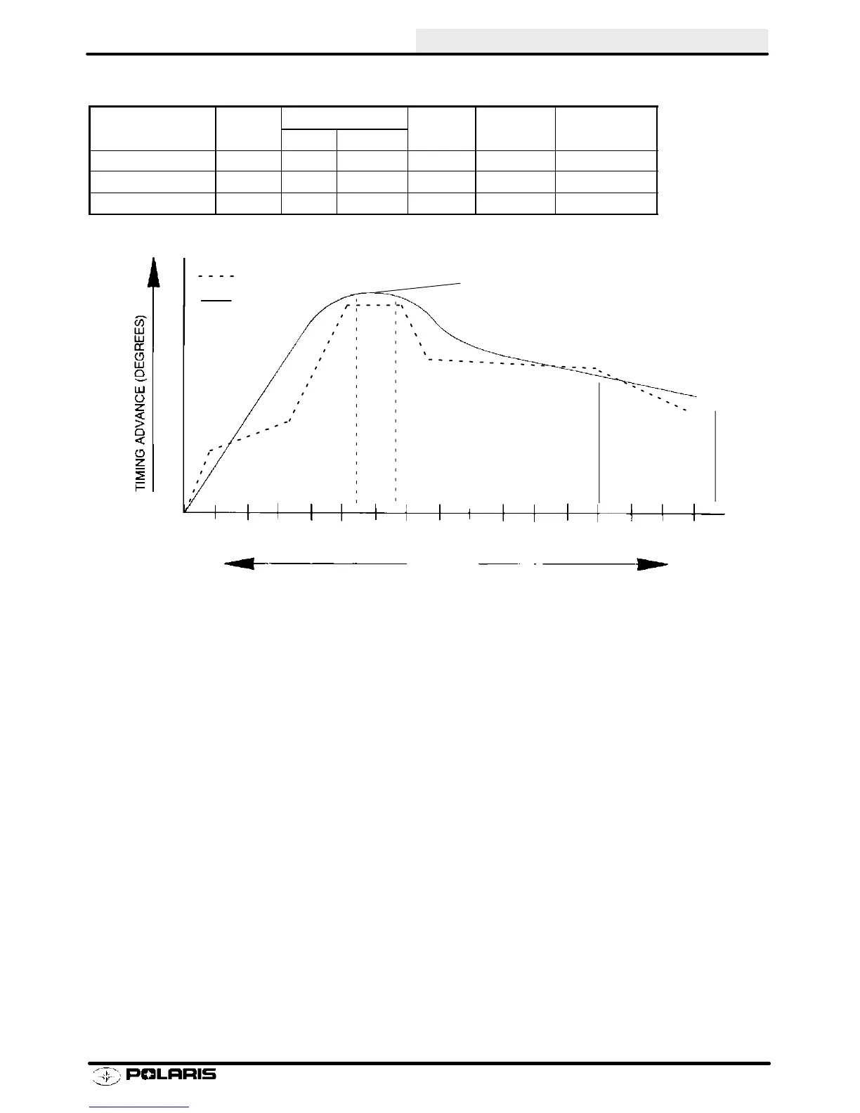
Ignition Timing
Operating RPM
(Depending On
Engine)
1000 2000 3000
4000 5000 6000
8000
7000
RPM
Maximum Advance
(Depending on Model)
Digital Timing
Analog Timing
NOTE: Always verify timing of engine at room temperature only (68q F/20q C, no engine warm up) and at the
proper RPM.
To obtain the best ignition timing accuracy and reduce the chance of error, the ignition timing specification is given
at a “flat” portion of the advance curve. This flat portion on the curve is where the ignition timing is specified.
Ignition timing must be checked at the specified RPM, or inaccurate timing will result. Refer to timing specifica-
tions at the beginning of this chapter.
Dial Indicating The Timing Marks
Due to differences between engines, it is necessary to dial indicate the timing marks on all engines before attempt-
ing to adjust the ignition timing. To indicate the marks:
1. Remove the mag (RH) cylinder spark plug and install the dial indicator.
2. Rotate the crankshaft by hand while observing the dial indicator. As the piston touches the indicator plunger,
the dial will begin to rotate. Find the point where the pointer stops rotating and reverses direction. This will be
TDC (Top Dead Center).
3. While holding the crankshaft with the piston at TDC, zero the indicator by rotating the bezel until the 0 on the
dial and the pointer align.
4. Rotate the crankshaft opposite the direction of rotation about .250 BTDC (2 1/2 pointer revolutions).
5. Determine the correct ignition timing position from the ignition data charts and rotate the crankshaft in the
normal direction of rotation to that position. (Example: If engine timing is .150 BTDC, the crankshaft must be
rotated in the normal direction of rotation so that the dial indicator pointer does one complete revolution and
stops on 50. This should be 1 1/2 pointer revolutions before top center, or .150 BTDC.
6. While holding the crankshaft at the correct timing position, mark the flywheel (with chalk or a white marker)
directly in-line with the stationary pointer (or line) on the fan or recoil housing through the timing inspection
window.
Enfocus Software - Customer Support
 Loading...