7.33
FINAL DRIVE
7
INSTALLATION
1. Slide shaft assembly into bearing carrier hub.
2. Apply anti-seize compound to splines of shaft.
3. Install a new lock ring and install the shaft.
4. Lift bearing carrier into place and install bolt to upper
control arm. Torque bolt to specification.
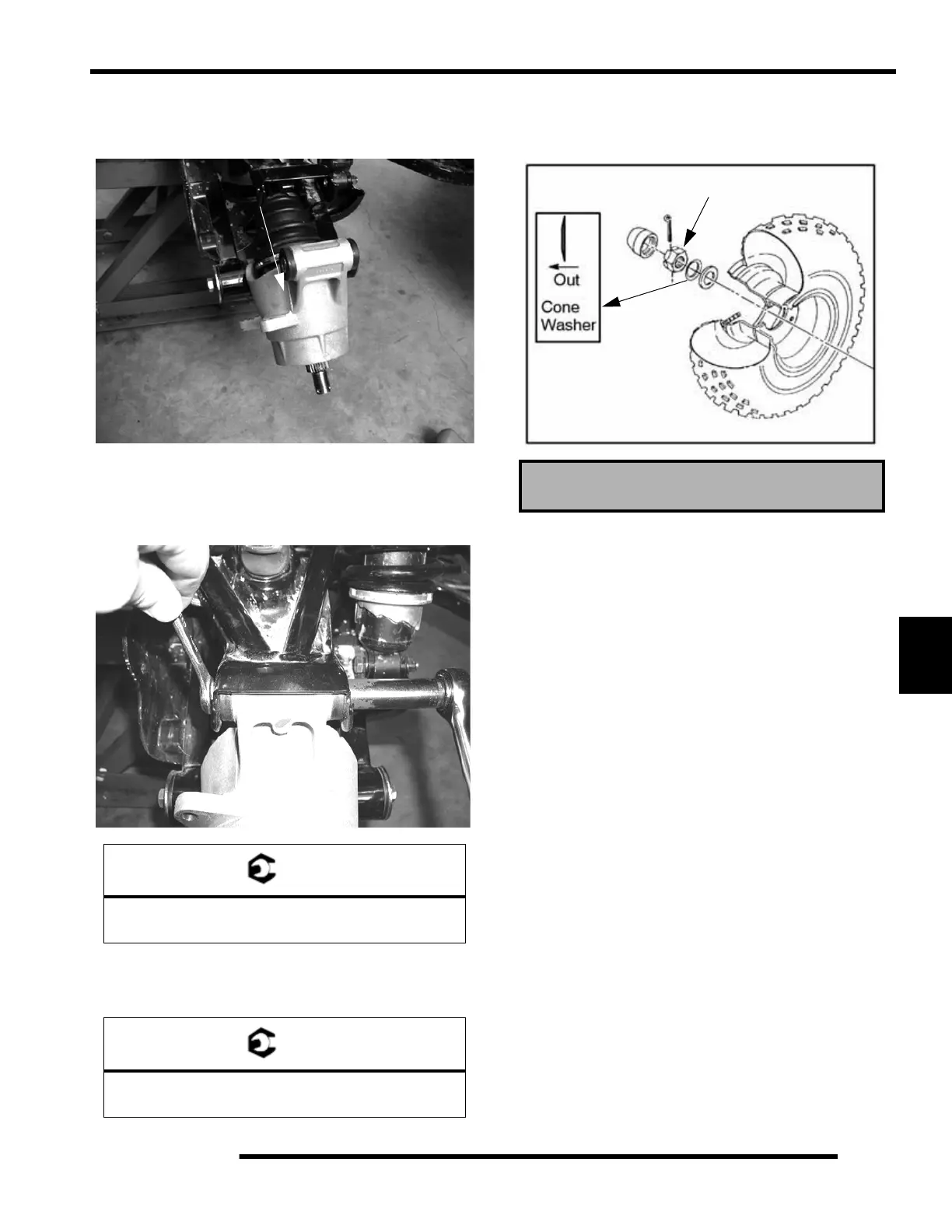
5. Install hub, flat washer, domed washer (domed side out)
and nut. Torque center hub nut to specification. Install new
cotter pin and hub cap.
6. Install brake caliper and tighten bolts to specification. Refer
to Chapter 9.
7. Install rear wheel and torque wheel nuts to specification.
8. Grease all fittings thoroughly with Premium U-Joint
Lubricant (PN 2871551).
Drive Shaft and CV Joint Handling Tips
Care should be exercised during driveshaft removal or when
servicing CV joints. Driveshaft components are precision parts.
Cleanliness and following these instructions is very important to
ensure proper shaft function and a normal service life.
• The complete driveshaft and joint should be handled by
getting hold of the interconnecting shaft to avoid
disassembly or potential damage to the driveshaft
joints.
• Over-angling of joints beyond their capacity could
result in boot or joint damage.
• Make sure surface-ground areas and splines of shaft are
protected during handling to avoid damage.
• Do not allow boots to come into contact with sharp
edges or hot engine and exhaust components.
• The driveshaft is not to be used as a lever arm to
position other suspension components.
• Never use a hammer or sharp tools to remove or to
install boot clamps.
• Be sure joints are thoroughly clean and that the proper
amount and type of grease is used to refill when joint
boots are replaced and when joints are cleaned. Refer
to text for grease capacity of CV joints and CV joint
boots.
= T
Upper Hub Carrier Bolt Torque:
37 ft. lbs. (50 Nm)
= T
Rear Hub Nut Torque:
80 ft. lbs. (109 Nm)
Refer to Page 7.2 for Wheel Nut Torque.
80 ft.lbs. (109 Nm)
 Loading...