10.34
ELECTRICAL
Differential Relay Operation
• The AWD switch must be turned to ‘TURF’ mode.
• Speed must be below 15mph and transmission must not
be in ‘Park’.
• 12Vdc is constant at the differential relay.
• ECU senses grounding on pin #26 from the AWD
switch.
• ECU grounds pin #13, activating the relay.
• Relay powers the differential solenoid.
• System must be grounded to operate.
Differential Relay Testing
• Test for 12Vdc constant at the relay with the AWD
switch turned to ‘TURF’ mode.
• Test for continuity to ground at pin #26 of the ECU
connector from the AWD switch.
• Test for continuity to ground at ECU pin #13.
• Test for continuity at ECU connector pin #13 to the
solenoid.
• Test the AWD/TURF switch for proper function.
IMPORTANT: Verify all wires and wiring connections
have been tested properly with a known good volt/
ohm meter before suspecting an ECU failure. 80% of
all electrical issues are caused by bad/failed
connections and grounds.
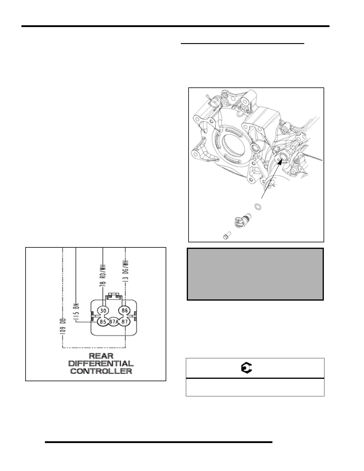
X2 / TOURING SPEED SENSOR
Testing
Using the special tools listed, test the speed sensor according to
the tester instructions. Remove sensor and inspect the o-ring
seal for damage or wear and replace as required. Replacement
of sensor is required as it is not serviceable.
Replacement
1. Remove the sensor retaining using a suitable tool.
2. Coat o-ring of new sensor with anti-seize compound or
sealant.
3. Push new sensor into gearcase housing. Install bolt and
tighten to specification.
Speed Sensor Special Tools:
Static Timing Light Harness
PN 2871745
Hall Sensor Probe Harness
PN 2460761
= T
Speed Sensor Bolt Torque
8-12 ft. lbs. (11-17 Nm)
 Loading...