10.41
ELECTRICAL
10
Starter Reassembly / Installation
1. Install brush plate to field magnet housing aligning index
tab.
2. Install O-ring, two small phenolic spacers, large phenolic
washer, flat washer, lock washer, and terminal nut.
3. While holding brush springs away from brushes, push
brushes back and hold in place.
4. Slide armature into field magnet housing. Release brushes.
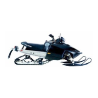
5. Lightly grease the drive roller bearing and reinstall drive
end frame on armature. Inspect seal for wear or damage.
Replace drive end cap if necessary.
6. Be sure wire insulation is in place around positive brush
wire and pushed completely into slot on phenolic plate.
7. Using Dielectric Grease (PN 2871329), lubricate brush end
bushing and install shims.
8. Align brush plate and install cover and screws.
9. Lightly grease pinion shaft and install pinion, spring
stopper, and snap ring.
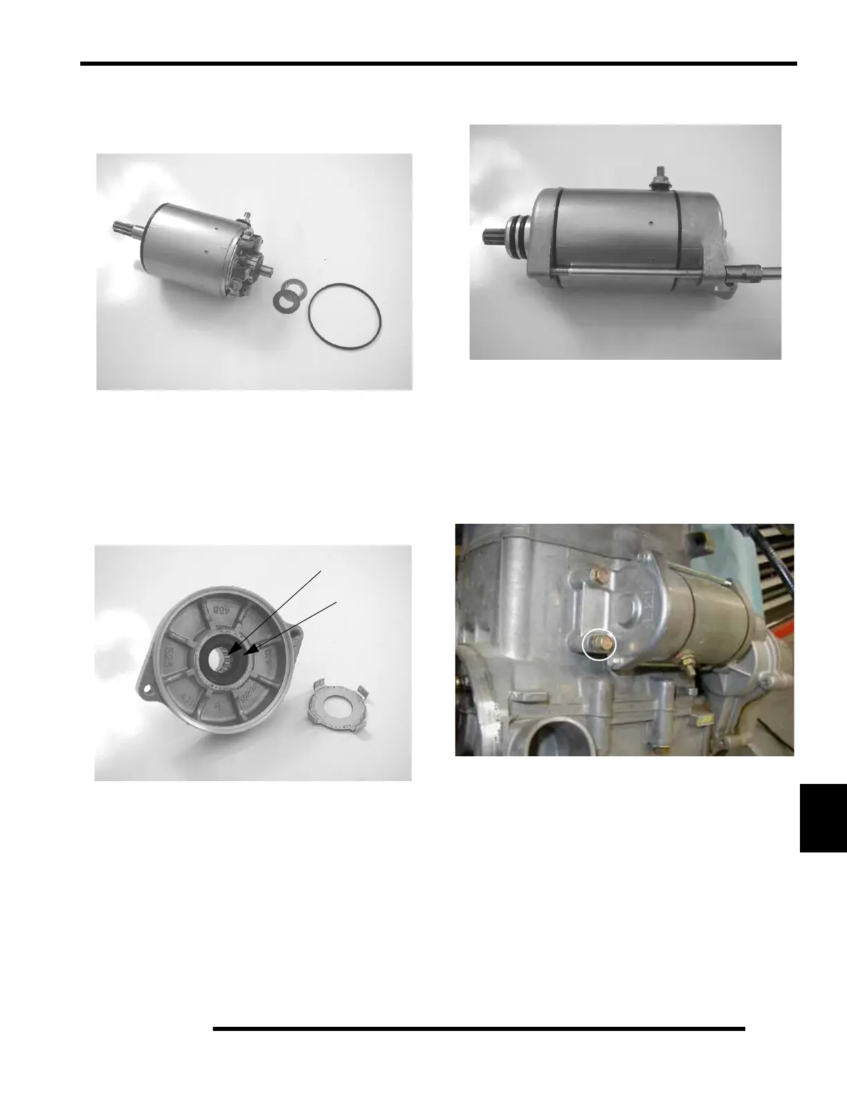
10. Install the starter onto the engine case. Hand tighten each
of the starter bolts. Torque the bottom bolt first to 9
ft.lbs. (12 Nm). Then torque the top bolt to the same
specification.
NOTE: It is important to tighten the bottom starter
bolt first (circle), as the bottom hole acts as a pilot
hole to properly align the starter drive (bendix) with
the flywheel. This helps to prevent binding and
starter damage.
Starter Solenoid Bench Test
To measure the resistance of the pull-in coil, connect one meter
lead to the solenoid lead wire and the other to ground. The
resistance should be 2.8-3.6 ohms. Refer to “Electric Starter
System Testing” in this section to further test the solenoid.
Roller Bearing
Seal

 Loading...