10.22
ELECTRICAL
BLACKOUT RELAY provides power to the following
system:
• Rear Differential Solenoid
CHARGING SYSTEM
Current Draw - Key Off
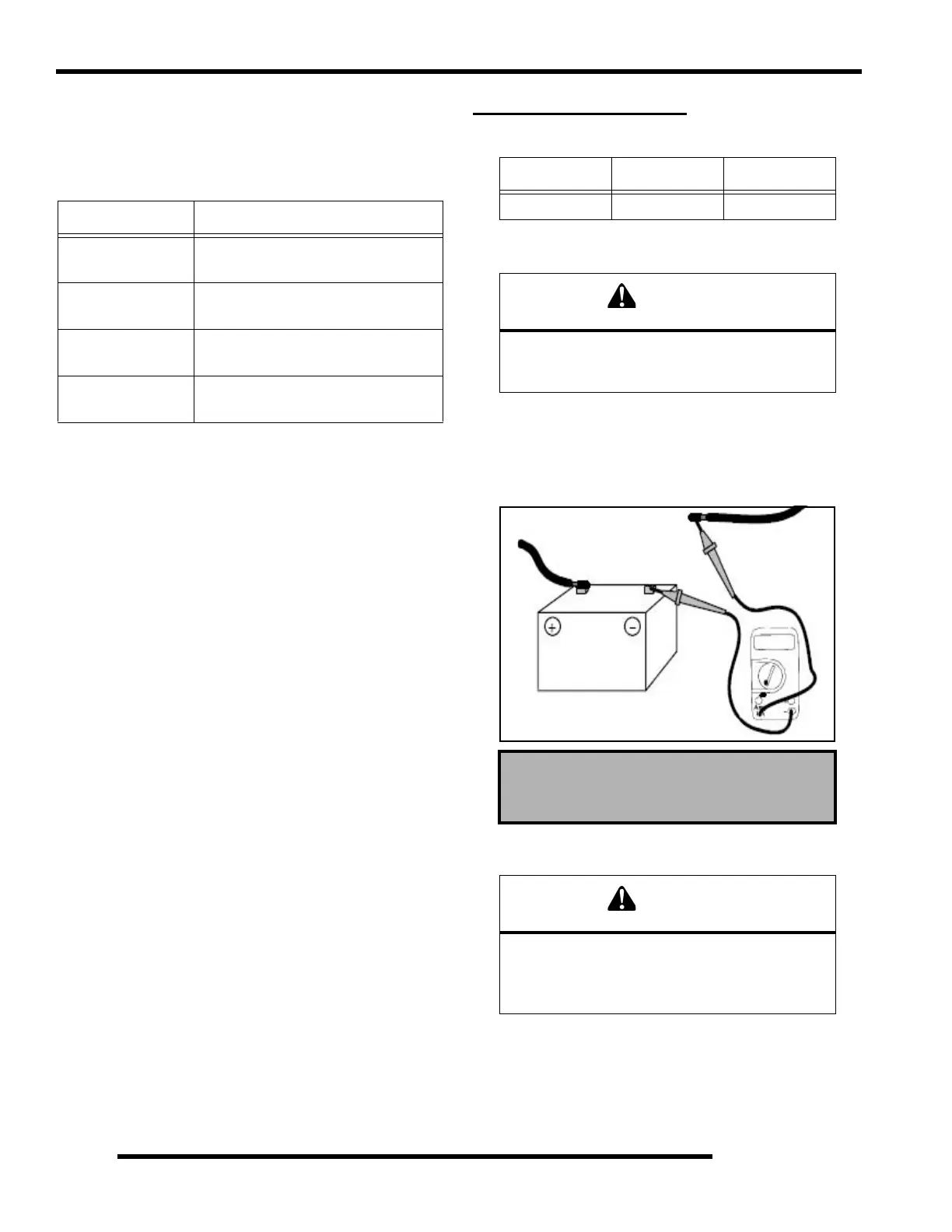
Connect an ammeter in series with the negative battery cable.
Check for current draw with the key off. If the draw is excessive,
loads should be disconnected from the system one by one until
the draw is eliminated. Check component wiring as well as the
component for partial shorts to ground to eliminate the draw.
Charging System “Break Even” Test
The “break even” point of the charging system is the point at
which the alternator overcomes all system loads (lights, etc.)
and begins to charge the battery. Depending on battery condition
and system load, the break even point may vary slightly. The
battery should be fully charged before performing this test.
BLACKOUT RELAY
COLOR FUNCTION
White
Ground input from Blackout Switch to
enable (open) relay
Red / Yellow
BUS Bar - 10-Amp fuse protected 12
Vdc battery voltage.
Red / Yellow
10-Amp fuse protected 12 Vdc battery
voltage.
Red / Yellow
Provides 12 Vdc power for all light
circuits.
Alternator Output
RPM AMPS VOLTS
2500 20 13.2 Vdc
Do not connect or disconnect the battery cable
or ammeter with the engine running. Damage will
occur to electrical components.
Current Draw - Key Off:
Maximum of .01 DCA (10 mA)
Do not allow the battery cables to become
disconnected with the engine running. Follow the
steps below as outlined to reduce the chance of
damage to electrical components.
Current Draw Inspection
Key Off
 Loading...