4.27
ELECTRONIC FUEL INJECTION
4
13. Lift the rear of the fuel tank up first and carefully pull it up
and out from the vehicle.
Fuel Tank Installation
1. Carefully reinstall the fuel tank assembly.
2. Reinstall the (2) fuel tank brackets and fasteners.
3. Reinstall the (3) shift lever support bracket fasteners.
4. Reinstall the rear RH fender well and secure with fasteners.
5. Reinstall the seat belt mechanism and secure the lower bolt
6. Reinstall the RH rocker panel and all previously removed
fasteners.
7. Reinstall the rear seat base assembly and secure with the (2)
fasteners
8. Reinstall the center console and shift knob.
9. Install the fuel line and vent hose and clamp; verify they are
secure.
10. Reconnect the fuel pump electrical harness.
11. Reconnect the negative battery cable. Test the fuel pump
by turning the ignition key on and listening for the pump
to activate. Check for leaks.
12. Finally, install the rear service panel along with the driver
and passenger seats.
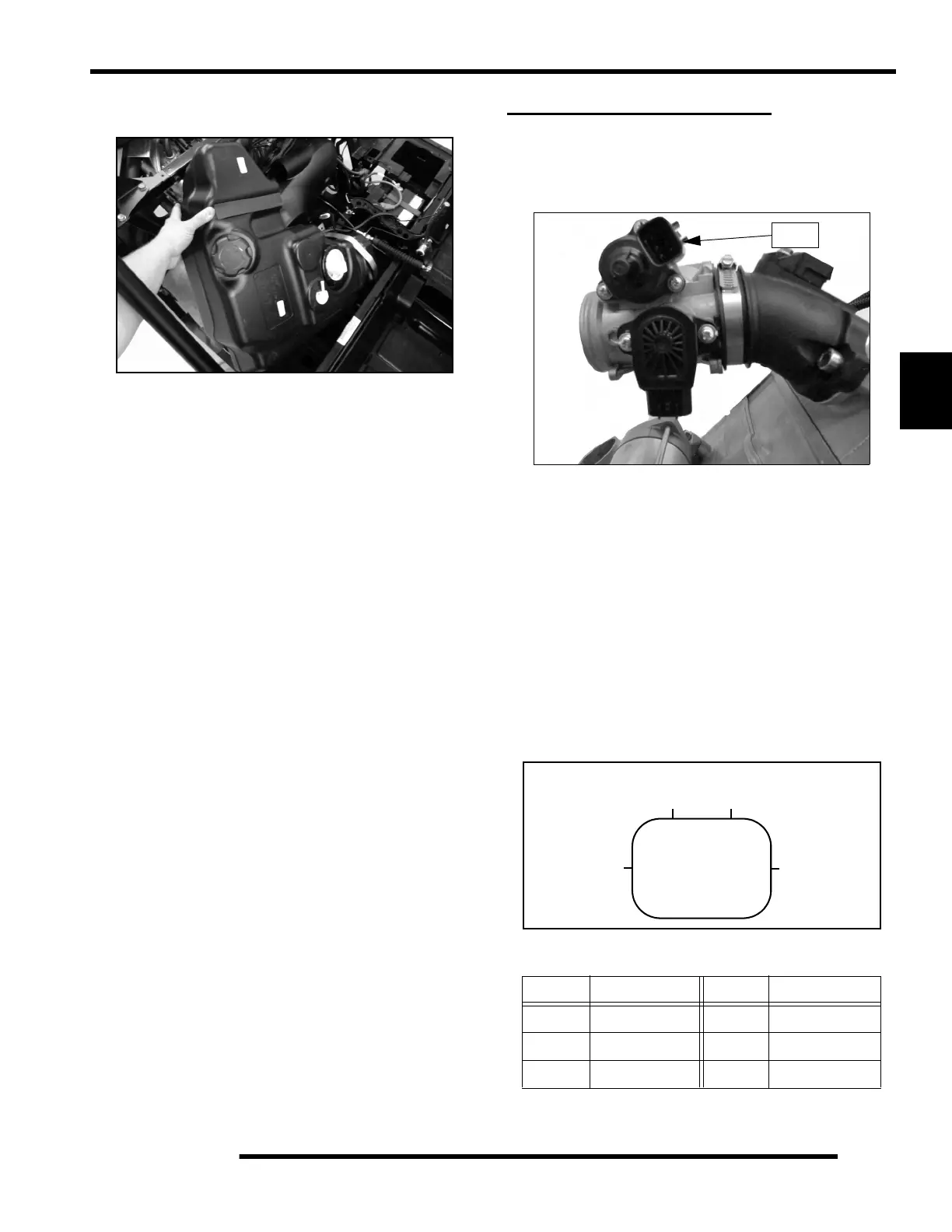
IDLE AIR CONTROL (IAC)
Operation Overview
The Idle Air Control (IAC) is used to stabilize the idle quality of
the engine at cold start-up and after warm-up operations.
Mounted on the throttle body, the IAC contains 1 stepper motor
which receives varying voltage signal pulses from the ECU.
These pulses determine the IAC plunger setting, thereby
controlling the amount of air bypassing the closed throttle body
for idle control. If the IAC is disconnected or inoperative, it will
remain at it’s last operated position.
IAC Test
The IAC is a non-serviceable item. If it is faulty, it must be
replaced. It can be ‘bench tested’ using the following method:
Set your meter to read Ohms. Check the resistance values at each
of the following pin locations of the IAC. If any of the readings
are out of specification, replace the IAC.
IAC Resistance Readings
Pins Resistance Pins Resistance
1 - 2 30 ± 1.2 4 - 5 30 ± 1.2
2 - 3 30 ± 1.2 5 - 6 30 ± 1.2
1 - 3 60 ± 2.4 4 - 6 60 ± 2.4
1
23
4
5
6
IAC Valve Connector
 Loading...