172
Chapter 5 Section I: Replacement Procedures
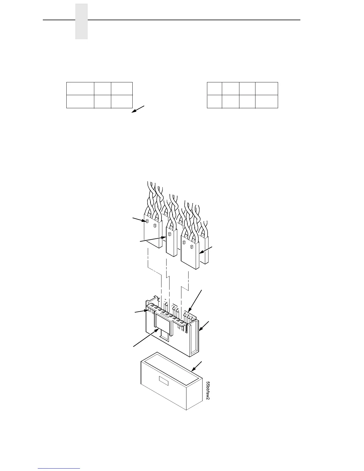
Figure 22. Cable Connector Coupling Shroud, Disassembly/Assembly
Typical 4-Wire
Cable Connector
Pull the sides outward just
enough to release the
connector key tab from the
slot in the connector
coupling shroud.
Connector coupling
shroud P106 / P107
P/N 202362-901
J106 or J107 on
Controller Board
Key Tab
Typical 2-Wire
Cable Connector
Key Tab Slot
Push here to
remove the
coupling shroud
from the controller
board.
CCF = Card Cage Fan
LRIB M = Left Ribbon Motor
LRP = Left Ribbon Guide
PLAT M = Platen Open Motor
PMD = Paper Motion Detector (Switch)
POD = Paper Out Detect (Switch)
EHF* = Exhaust Fan
HBF = Hammer Bank Fan
JMP = Jumper Wire
MPU = Magnetic Pickup
PAPR M = Paper Feed Motor
PLO = Platen Open (Switch)
RRIB M = Right Ribbon Motor
RRP = Right Ribbon Guide
* JMP on pedestal models: used as a
spacer
P106 Connector Configuration P107 Connector Configuration
8 6 4 2
7 5 3 1
12 1020 18 16 14
11 919 17 15 13
LRIB M
PLAT M
LRP
CCF
PMD
POD
RRIB M
PAPR M
HBF
EHF
CVO
MPU
RRP
PLO
Pin No.
8 6 4 2
7 5 3 1
12 1020 18 16 14
11 919 17 15 13
Connectors are viewed
from the top, as seen
when plugged into
controller board.