275
Main Wire Harness Test Tables
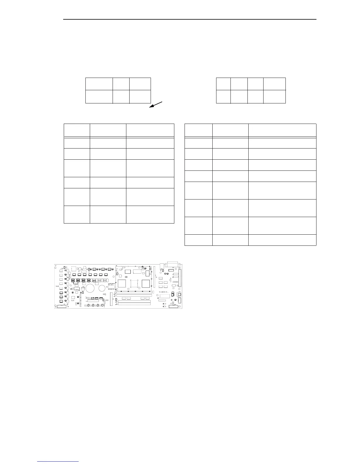
Device P106 Pins Normal
LRIB M 2, 4 and 6,8 7.2 - 8.8 Ω
PLAT M 1, 3 and 5, 7 1.35 - 1.65 Ω
LRP 10, 12 Open across pins
Short across post
CCF 9, 11 4.6 KΩ
PMD 14, 16
18, 20
8 Meg Ω
Open
POD 13, 15
17, 19
8 Meg Ω
Open
J106 J107
CCF = Card Cage Fan
LRIB M = Left Ribbon Motor
LRP = Left Ribbon Guide
PLAT M = Platen Open Motor
PMD = Paper Motion Detector (Switch)
POD = Paper Out Detect (Switch)
8 6 4 2
7 5 3 1
12 1020 18 16 14
11 919 17 15 13
LRIB M
PLAT M
LRP
CCF
PMD
POD
Pin No.
7 5 3 115 1319 17
RRIB M
PAPR M
HBF
EHF
CVO
MPU
RRP
PLO
CVO = Cover Open Switch
EHF* = Exhaust Fan
HBF = Hammer Bank Fan
MPU = Magnetic Pickup
PAPR M = Paper Feed Motor
PLO = Platen Open (Switch)
RRIB M = Right Ribbon Motor
RRP = Right Ribbon Guide
* Only in cabinet models
Device P107 Pins Normal
RRIB M 2, 4 and 6,8 7.2 - 8.8 Ω
PAPR M 1, 3 and 5, 7 0.417 - 0.681 Ω
HBF 10, 12 2.7 KΩ
EHF 9, 11 4.6 KΩ
RRP 14, 16 Open across pins
Short across post
PLO 13, 15 Continuity: switch closed
Open: switch open
CVO 18, 20 Continuity: switch closed
Open: switch open
MPU 17, 19 670 Ω
P106 Connector P107 Connector
Resistance
Resistance
11 9
8 6 4 216 1420 18 12 10
Connectors are viewed
from the top, as seen
when plugged into CMX
controller board.
MOTOR NOTES:
All Motors: Wait until motor has cooled to room temperature before testing. Use the table values to test for
winding continuity and for no shorts between winding and the motor frame. Rotate the motor by hand and
test for shorts; replace the motor if you find any shorts.
Shuttle Motor = approx. 0.7 Ω phase to phase; infinite resistance phase to motor frame. Wait until motor
has cooled to room temperature before testing. Use this value to test for winding continuity and for no shorts
between windings and the motor frame. Rotate the motor by hand and test for shorts; replace the shuttle
frame assembly if you find any shorts.
All fans have brushless DC motors powered by solid-state circuits and controlled by feedback from a fan
rotor position Hall Effect sensor. Fans driven by +48V measure 4 - 5 KΩ. Fans driven by +24V measure 2 - 3
KΩ. A very low reading can mean one of the winding drive transistors is shorted. An open circuit could
indicate defective fan electronics or an open cable. Fans will run whenever +48V is present; failure to run
can mean a defective cable, connector, or current sense resistor on the controller board. An open circuit
current sense resistor (on the controller board) will prevent the fan from running but will not allow software to
detect the fault.
NOTE: For cable shell
connector assembly and
disassembly, see page 171.