202
Chapter 5 Section I: Replacement Procedures
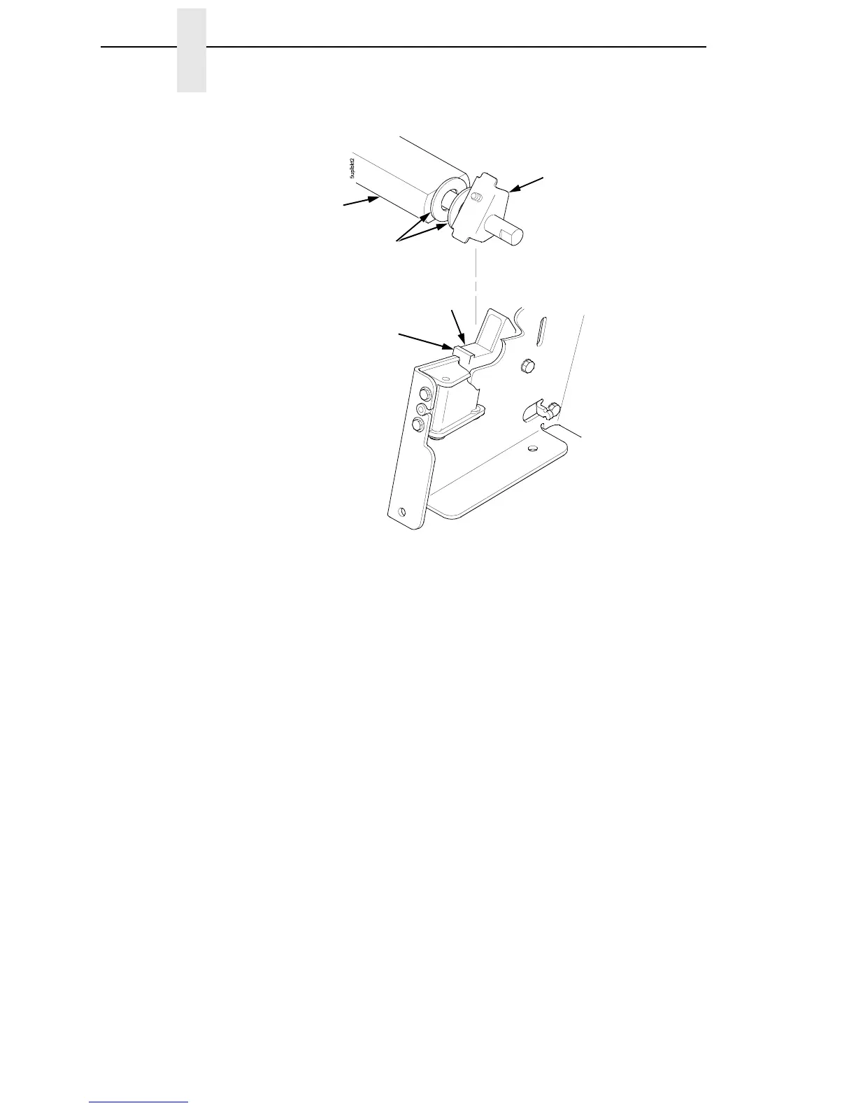
Figure 29. Positioning the Platen Adjust Brackets
9. Slide the right ribbon guide assembly into the side plate and install the
two 7/32 inch screws and washers. (See Figure 43, items 7, 8, and 9.)
10. Install the forms thickness indicator plate:
a. Slide the indicator plate, with the interlock switch assembly attached,
onto the platen shaft and up against the right side plate.
b. Install the Phillips #1 screw and washer securing the indicator plate.
11. Install the black metal washer onto the left side of the platen shaft. (See
page 242, item 26.)
12. Apply bearing lubricant to the nylon bearings in the two spring links, slide
the spring links onto the platen shafts, and connect the springs to the
spring hooks in the side plates. (See page 242, items 16, 17, and 18.)
13. Apply bearing lubricant to the platen shafts on both sides, between the
ends of the platen and the platen adjust brackets.
14. Install the paper ironer bracket. (See Figure 28.)
a. With the flat part of the bracket facing the front of the printer, place
the two hooks of the upper part of the paper ironer over the platen
shafts.
The left hook of the paper ironer bracket goes between the left platen
adjustment bracket and the platen.
On the right side of the platen, a washer goes on both sides of the
paper ironer bracket hook and the hook goes to the left of the right
platen adjustment bracket. (See Figure 28.)
Platen Adjust
Bracket
Washers
Platen
Wear
Saddle
Mechanism
Base Platen
Seat