Shaft, Splined
213
Installation
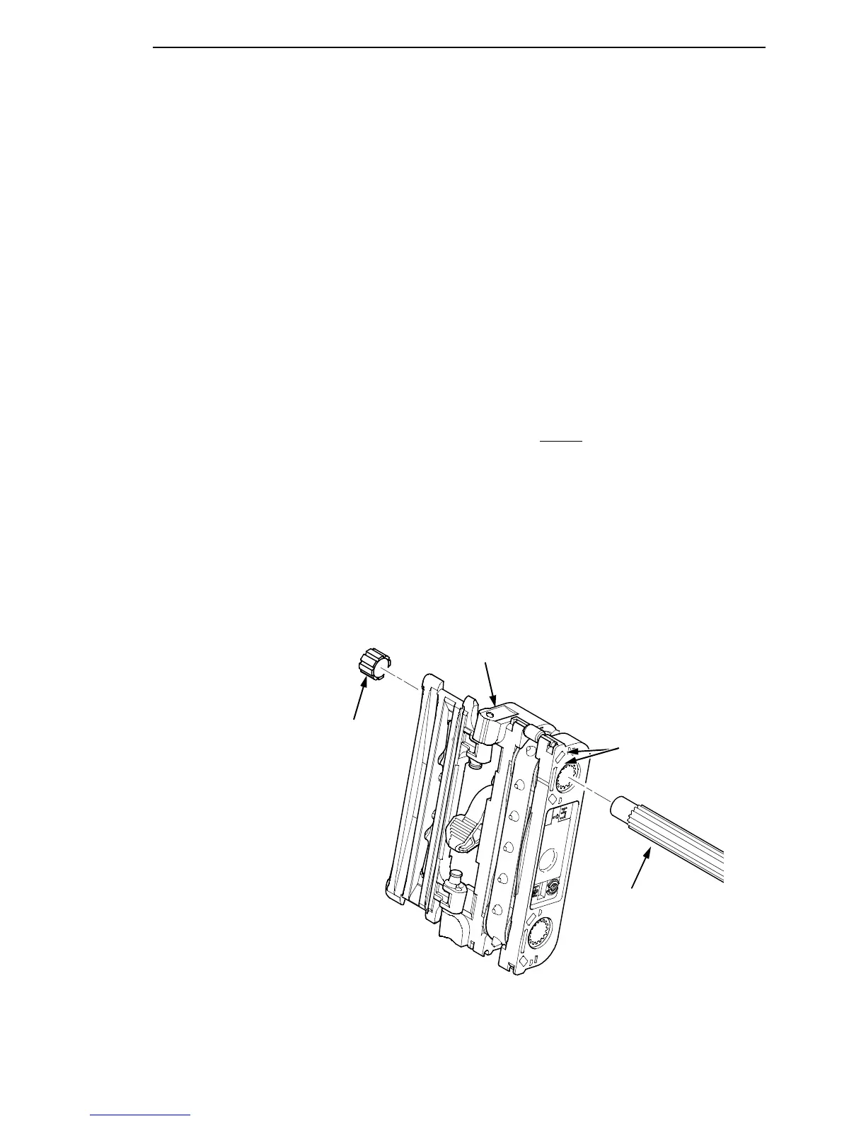
1. Open the doors on the left and right tractors. Position the tractor belts so
the alignment marks are at the top on both tractors. (See Figure 31.)
2. Slide the splined shaft through the right side plate and tractors. Make sure
the same spline passes the marked groove on each tractor. (See Figure
31.)
3. Install the tolerance ring on the left end of the splined shaft (page 240,
item 5).
4. Insert the tolerance ring lead-in portion into the sealed ball bearing in the
left tractor shaft plate (page 240, items 3, 5, and 6) while sliding the ball
bearing into the right side plate. Push the splined shaft to the left until the
flange on the ball bearing is in solid contact with right side plate. The
splined shaft will protrude about 1/16 inch from the ball bearing.
5. Install the right tractor shaft plate and screw (page 240, items 7 and 8) by
first sliding the upper “fingers” up and against the flange on the ball
bearing, then sliding the rectangular cutout over the support shaft end,
then snapping the U-shaped “spring” behind
the tab on the right side
plate.
6. Install the paper feed timing belt (page 168).
7. Set the paper feed timing belt tension (page 134).
8. Install the paper supports on the splined and support shafts. (See page
240, item 4.)
9. Insert the lower ends of the paper supports into the groove in the upper
forward edge of the platen.
10. Return the printer to normal operation (page 133).
Figure 31. Splined Shaft and Tractor Installation
Splined Shaft
NOTE: Align the marks on
both tractors before inserting
the splined shaft.
Tractor
Alignment Marks
Tolerance Ring