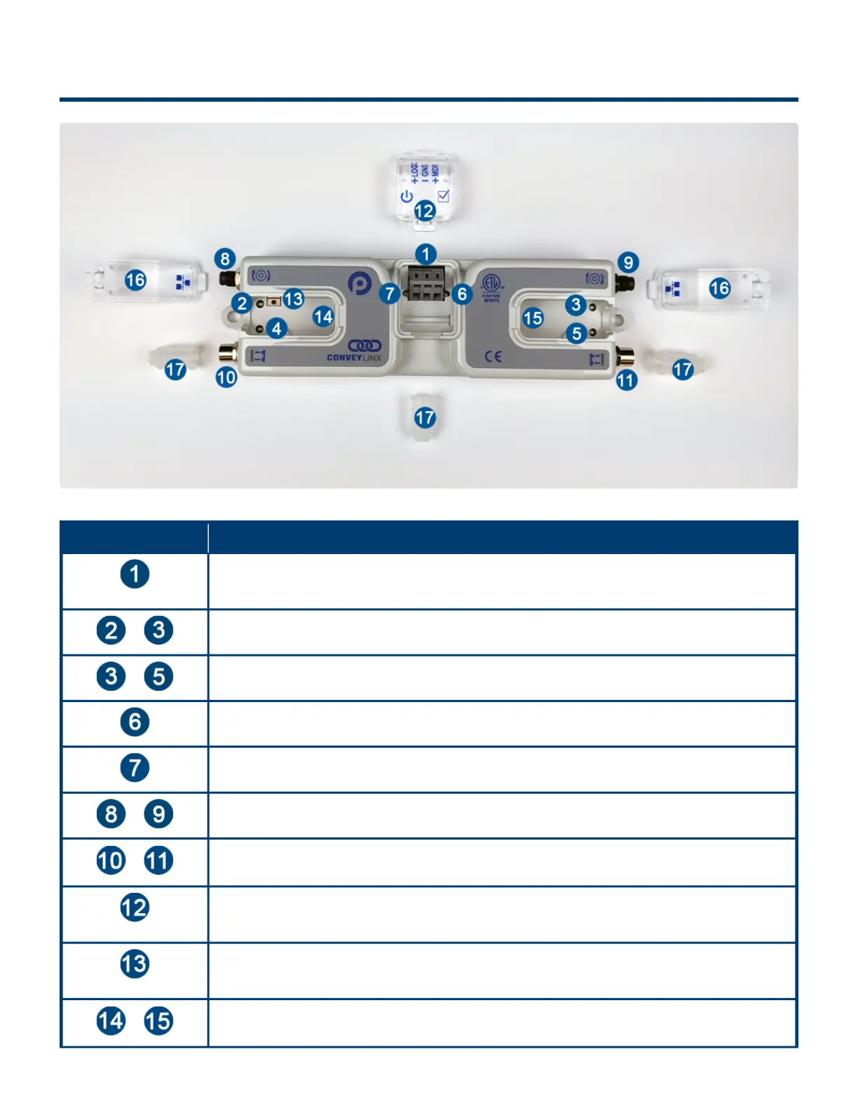
4.1. Identifying Module Components
Item Description
24VDC Power Terminals with separate connections for Logic and Motors
&
Motor Left LED & Motor Right LED – Motor status indicators
&
Left Sensor & Right Sensor Status LED Indicators
Module Status LED Indicator
Module Power LED Indicator
&
Motor Left and Motor Right Port – 4-pin M8 style connector for MDR connection
&
Sensor Left and Sensor Right Port – M8 style connector for zone photo-sensor
connection
Removable IP54 Power Compartment Cover
Module Replacement Button
&
Link Left and Link Right – RJ-45 style Ethernet network connection between modules
including LED Indicators
PULSEROLLER ConveyLinx-Ai2 User's Guide - 1.7
Page 11 of 154