4.8. LED Status Indicators
Ai2 Module status is indicated by several LED’s. All LED’s with the exception of the Ethernet Link and
Activity LEDs are multi-colored and context sensitive. The following sections indicate the various meanings
of all LED indicators.
If you need help finding where LED Items are located on the Ai2 Module
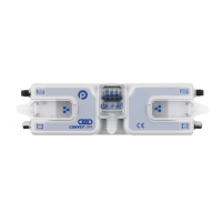
Communications
Indicator Item LED State Description
Ethernet Left
Link &
Ethernet
Right Link
&
OFF No connection established
Solid Green Connection is established
Blinking Green When data transmission activity is occurring
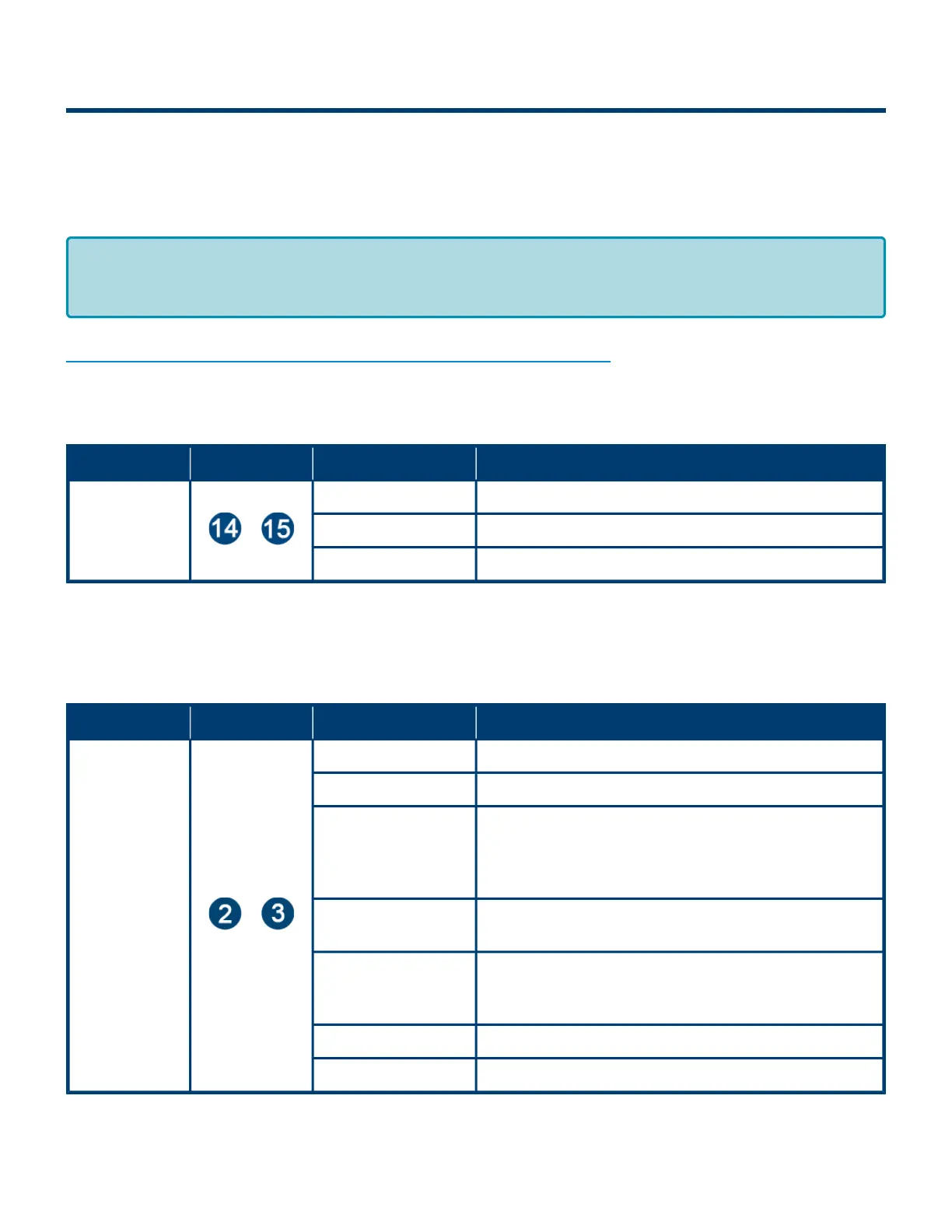
Motors
Indicator Item LED State Description
Motor Left &
Motor Right
&
OFF Motor is not running and no faults detected
Solid Green Motor is running
Solid Red
If Motor is running – indicates current limit
If Motor is stopped – indicates motor is not connected
properly or is overheated
Power supply is under 18V or above 30V
Blinking Red
Motor is overloaded and the module is limiting current
to reduce temperature
Flashing Red
Motor short circuit detected between at least two of
the phase windings or Motor Power supply is less
than 10V
Solid Amber Module is booting up
Slow Blinking Red Profinet enabled discover function initiated from PLC
By definition Blinking is approximately 1⁄2 second on/off cycle and Flashing is
approximately 1⁄4 second on/off cycle.
*
PULSEROLLER ConveyLinx-Ai2 User's Guide - 1.7
Page 26 of 154