EasyManuals Logo

Pulseroller ConveyLinx-Ai2 User Manual

Pulseroller ConveyLinx-Ai2
156 pages
To Next Page IconTo Next Page
To Previous Page IconTo Previous Page
Page #20 background imageLoading...
Page #20 background image
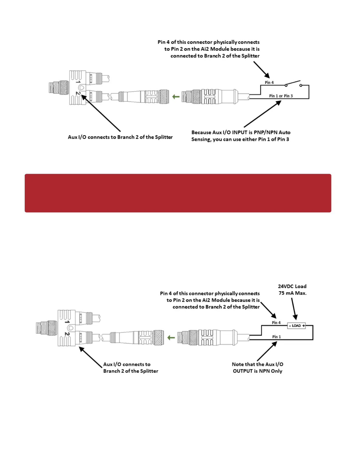
Aux I/O Pin 2 Input Connection Diagram
Aux I/O Pin 2 as Output
When the Aux I/O Pin 2 is configured as an output, the circuit is NPN only and requires the load to be
connected to Pin 1 (+24V)
Aux I/O Pin 2 Output Connection Diagram
Last modified: Aug 18, 2020
Because the auto-sensing circuit requires a nominal voltage in order to operate, there will
be some small amount of leakage current possible between Module Pin 2 and Pin 3 (GND).
Please use caution if you connect a load between Module Pin 2 and Pin 3.
!
PULSEROLLER ConveyLinx-Ai2 User's Guide - 1.7
Page 18 of 154

Table of Contents

Other manuals for Pulseroller ConveyLinx-Ai2

Questions and Answers:

Question and Answer IconNeed help?

Do you have a question about the Pulseroller ConveyLinx-Ai2 and is the answer not in the manual?

Pulseroller ConveyLinx-Ai2 Specifications

General IconGeneral
BrandPulseroller
ModelConveyLinx-Ai2
CategoryControl Unit
LanguageEnglish