Instrument Functions
R&S
®
NRP2
163User Manual 1173.9157.02 ─ 03
With multipath power sensors (R&S NRP-Z11, R&S NRP-Z21/22/23/24/28, R&S NRP-
Z31 and R&S NRP-Z91/92/98), the R&S NRP2 displays the test result of each individual
path separately.
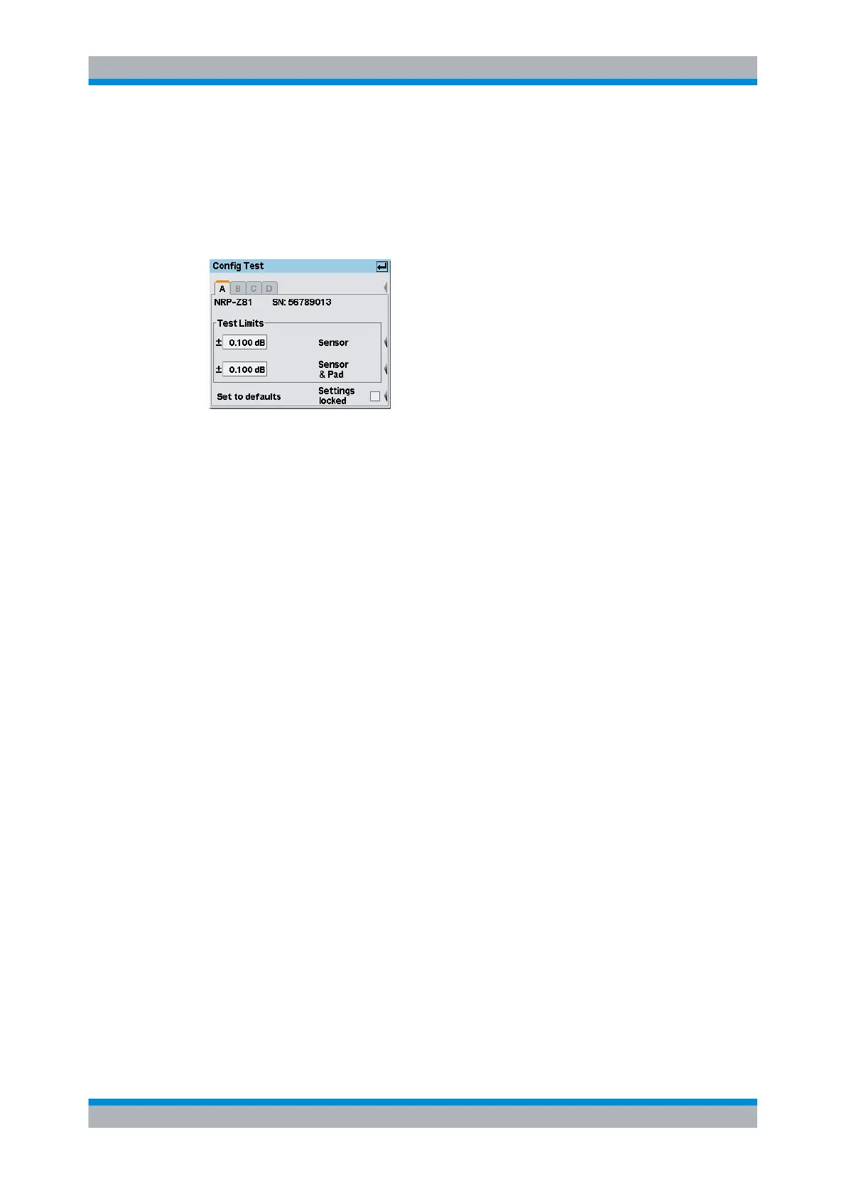
Config…
Open the dialog box for entering tolerance limits.
Fig. 4-99: Config Test dialog box
Exceeding the tolerance limits will result in a test failure. The factory-set default settings
depend on the sensor and are in line with the data sheet values. They are applicable in
the entire ambient temperature range. If the base unit and the sensors are not used at
temperature extremes, the tolerance limits can be restricted so that any damage to the
sensor can be detected even more quickly.
Test Limits ← Config…
Defines the test limit range.
"Sensor"
Tolerance limits for the sensor section only.
"Sensor & Pad"
Tolerance limits for the combination of the sensor section with attached
attenuator.
Set to defaults ← Config…
Resets the factory-set default settings.
Settings locked ← Config…
Protects the settings against being changed by mistake.
4.8 Messages and alarms
The R&S NRP2 displays a variety of different messages such as status messages, error
messages, warnings or information on the screen, some in separate windows, or in the
header.
Messages and alarms