Putting into Operation
R&S
®
NRP2
17User Manual 1173.9157.02 ─ 03
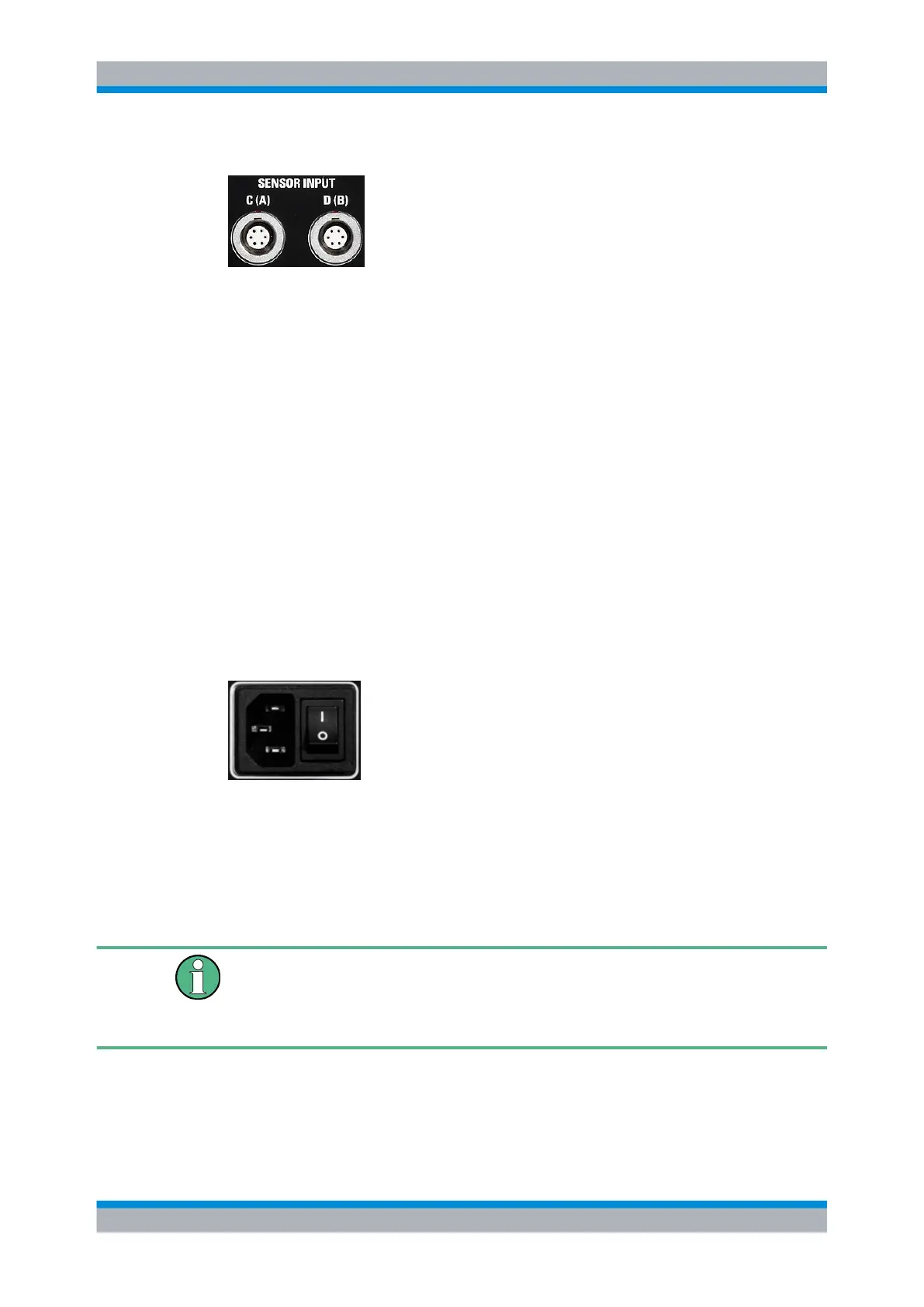
Sensor connectors
Optional sensor connectors C and D (option R&S NRP-B5) can be installed at the rear
panel. Alternatively, sensor connectors A and B can be retrofitted from front to rear panel
(option R&S NRP-B6).
1.7 Connecting the instrument to the AC supply
The AC supply and power switch are at the rear of the unit.
When the R&S NRP2 is connected to the AC supply, it automatically sets itself to the
correct range for the applied voltage (range: see type label). There is no need to set the
voltage manually.
The power switch can be set to two positions:
●
0:
The instrument is disconnected from the mains.
●
I
The instrument is power-supplied. It is either ready for operation (STANDBY) or in
operating mode, depending on the color of the Status LED on the front panel.
Fig. 1-5: AC supply connector at the rear of the meter
► Connect the instrument to the AC power source using the AC power cable delivered
with the instrument.
Note: The instrument is in compliance with safety class EN61010-1. Connect the
instrument only to a socket with earthing contact.
AC supply voltage
The R&S NRP2 can be operated from AC lines with a voltage range of 100 V to 240 V
and a frequency range of 50 Hz to 60 Hz. Note that a restricted voltage range
(100 V to 120 V) applies to 400 Hz networks.
Connecting the instrument to the AC supply