Putting into Operation
R&S
®
NRP2
15User Manual 1173.9157.02 ─ 03
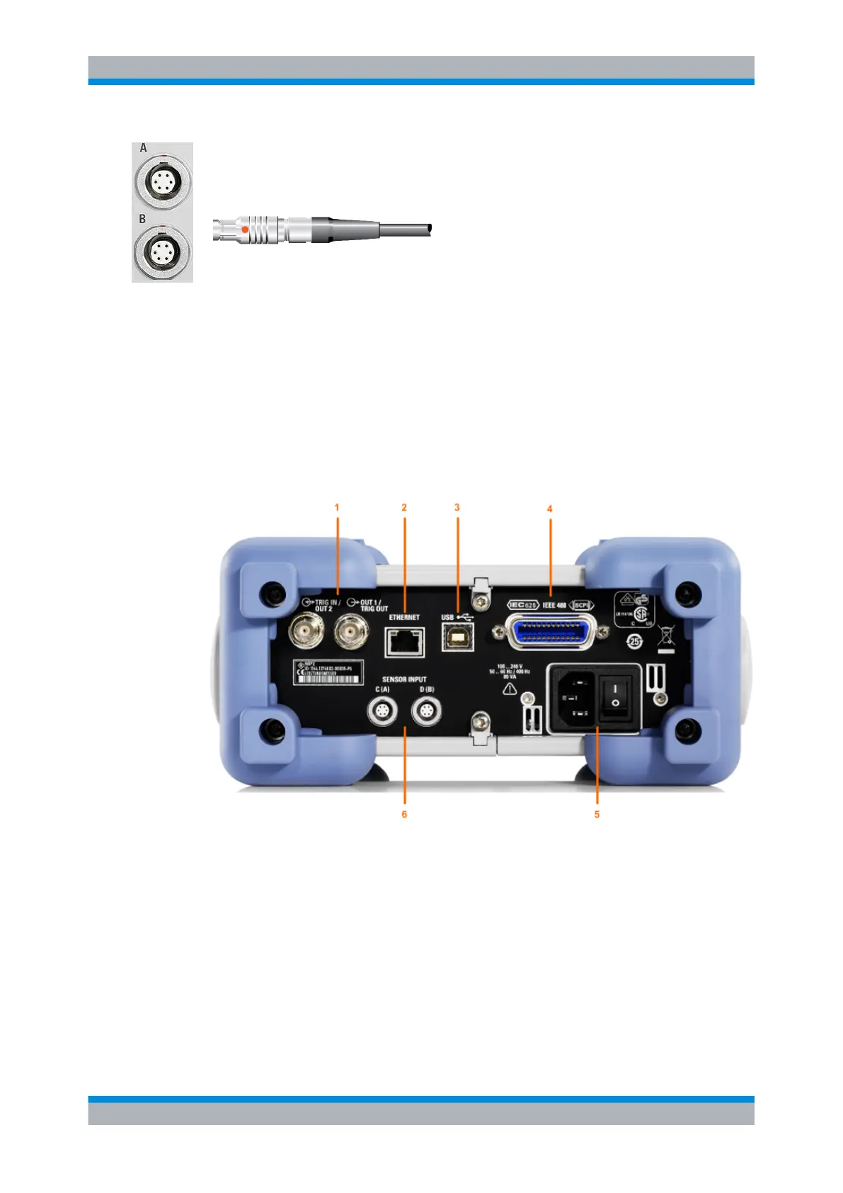
Sensor connectors
The front panel accommodates a maximum of two sensor connectors (for sen-
sors A and B).
The power sensors are connected by inserting the male connector.
Note: You can not disconnect the sensor simply by pulling at the cable or the rear part
of the connector. To disconnect pull the connector at its sleeve, which is marked with a
red dot.
1.6 Rear Panel
This section gives an overview of the control elements and the connectors on the rear
panel of the R&S NRP2. Each element and connector is briefly described and a reference
is given to the chapters containing detailed information.
Fig. 1-4: Rear panel view
1 = TRIG IN / OUT2 and OUT1 / TRIG OUT connectors
2 = ETHERNET interface
3 = USB interface
4 = IEC 625/IEEE 488 interface
5 = AC supply and power switch
6 = Sensor connectors (option R&S NRP-B5)
Rear Panel