Putting into Operation
R&S
®
NRP2
16User Manual 1173.9157.02 ─ 03
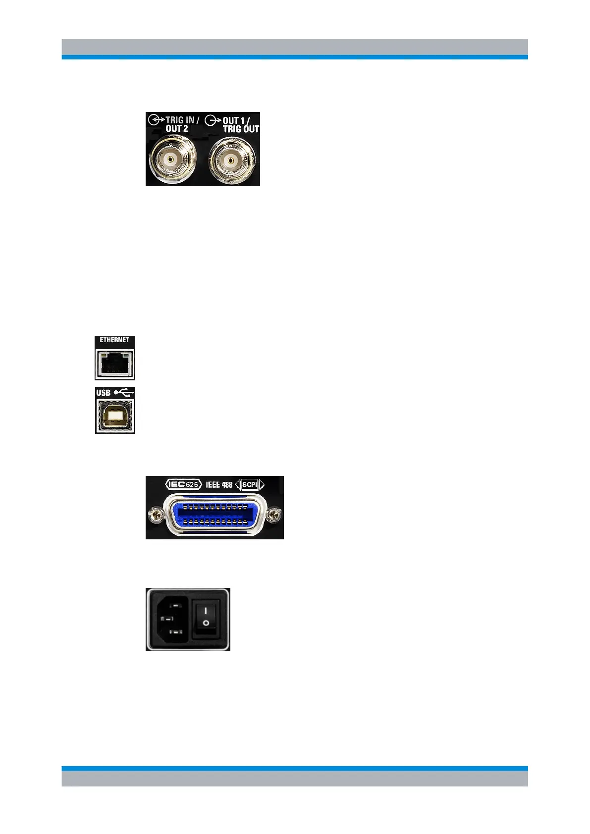
TRIG IN / OUT2 and OUT1 / TRIG OUT
The BNC connector OUT1 / TRIG OUT outputs an analog signal with a voltage between
0 V and 3.3 V. It can be used to output a voltage that is proportional to the measured
value (e.g. for level regulation) or a digital signal for threshold monitoring.
If configured as trigger output, the trigger signal of a power sensor can be supplied. In
this case, the power sensor must be set as trigger master.
The BNC connector TRIG IN / OUT2 can be used either as an external trigger input or
as a second analog output.
The inputs/outputs are configured in the "System" menu, see chapter 4.7.2, "Setting the
analog outputs and the trigger input", on page 149.
ETHERNET
The Ethernet connector is an RJ45 socket for remote controlling the R&S NRP2 via a
network.
USB
USB (Universal Serial Bus) interface of type B. This connector is used for remote control
of the instrument (see chapter 5.2, "Connecting a Controller to the Base Unit",
on page 168) and to update the firmware of the instrument by means of PC downloads
(for more information, see the service manual, chapter 4).
IEC 625/IEEE 488
The IEC/IEEE bus connector to IEEE488 is used to remote control the R&S NRP2.
AC supply and power switch
For detailed information on the AC supply, see chapter 1.7, "Connecting the instrument
to the AC supply", on page 17 .
Rear Panel