Instrument Functions
R&S
®
NRP2
149User Manual 1173.9157.02 ─ 03
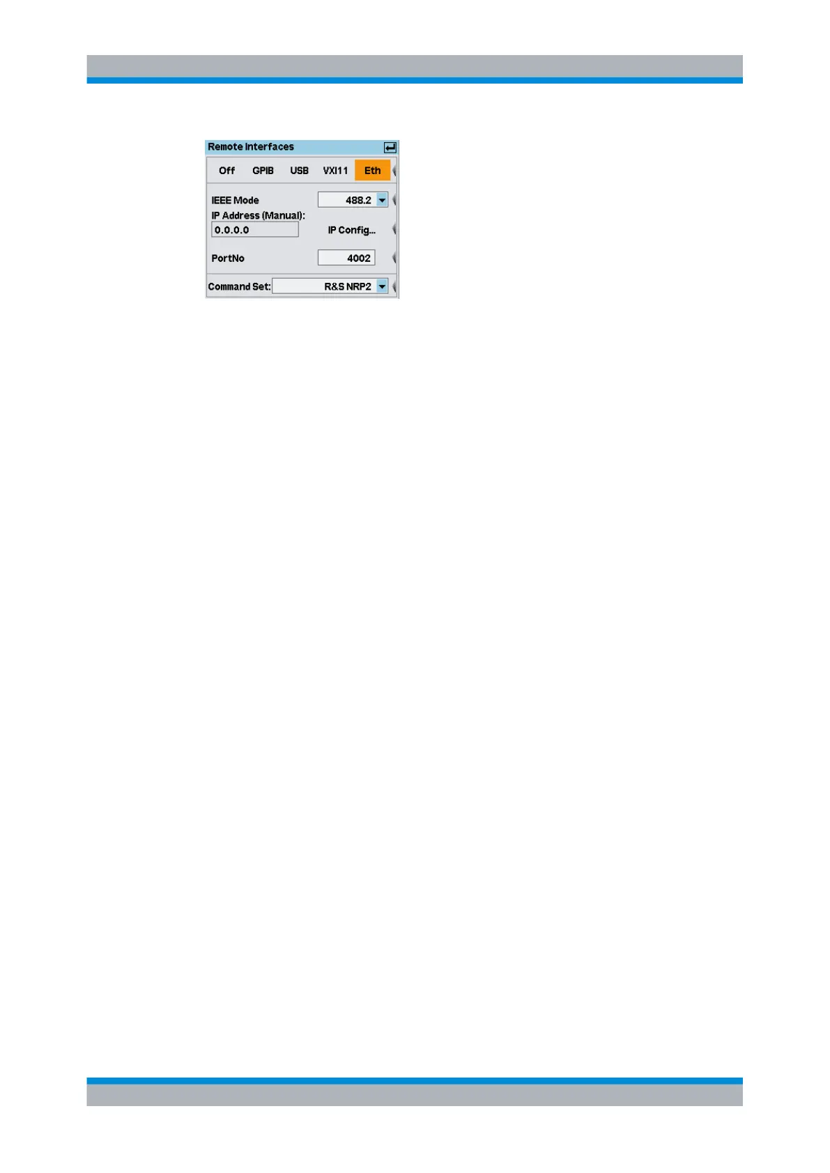
Fig. 4-79: Remote Interface dialog box, Ethernet
IEEE Mode
Selects the level of standardization of the IEEE bus interface. The R&S NRP2 supports
all versions of "IEEE 488.0, *.1 and *.2".
IP Address (Manual / DHCP)
Shows the IP address and indicates whether it is assigned manually or automatically. Set
the address in the "IP Config" dialog box.
IP Config...
Opens the subdialog for configuring the IP address, see "IP Address (Manual / DHCP)"
on page 147.
PortNo
Inserts the port number configured for remote-control.
Command Set
Selects the instrument type for emulation, see "Command Set" on page 145.
4.7.2 Setting the analog outputs and the trigger input
There are two multifunction BNC connectors at the rear of the R&S NRP2 (TRIG IN /
OUT2 and OUT1 / TRIG OUT). They can be used as either trigger input or trigger output,
or as analog output. If used as analog output they either output a signal that is proportional
to the measured value or a TTL signal for threshold monioring. The functions of these
connectors are specified in the "I/O" dialog box.
► To open the "I/O" dialog box, select "I/O..." in the "System" menu.
System settings
 Loading...


