Instrument Functions
R&S
®
NRP2
150User Manual 1173.9157.02 ─ 03
Fig. 4-80: I/O dialog box
For background information on the analog outputs see chapter 4.7.2.3, "Voltage at the
analog outputs", on page 155.
4.7.2.1 Out1 interface
This section describes the functions of the analog signal output at the "OUT1 / TRIG
OUT" connector and their settings.
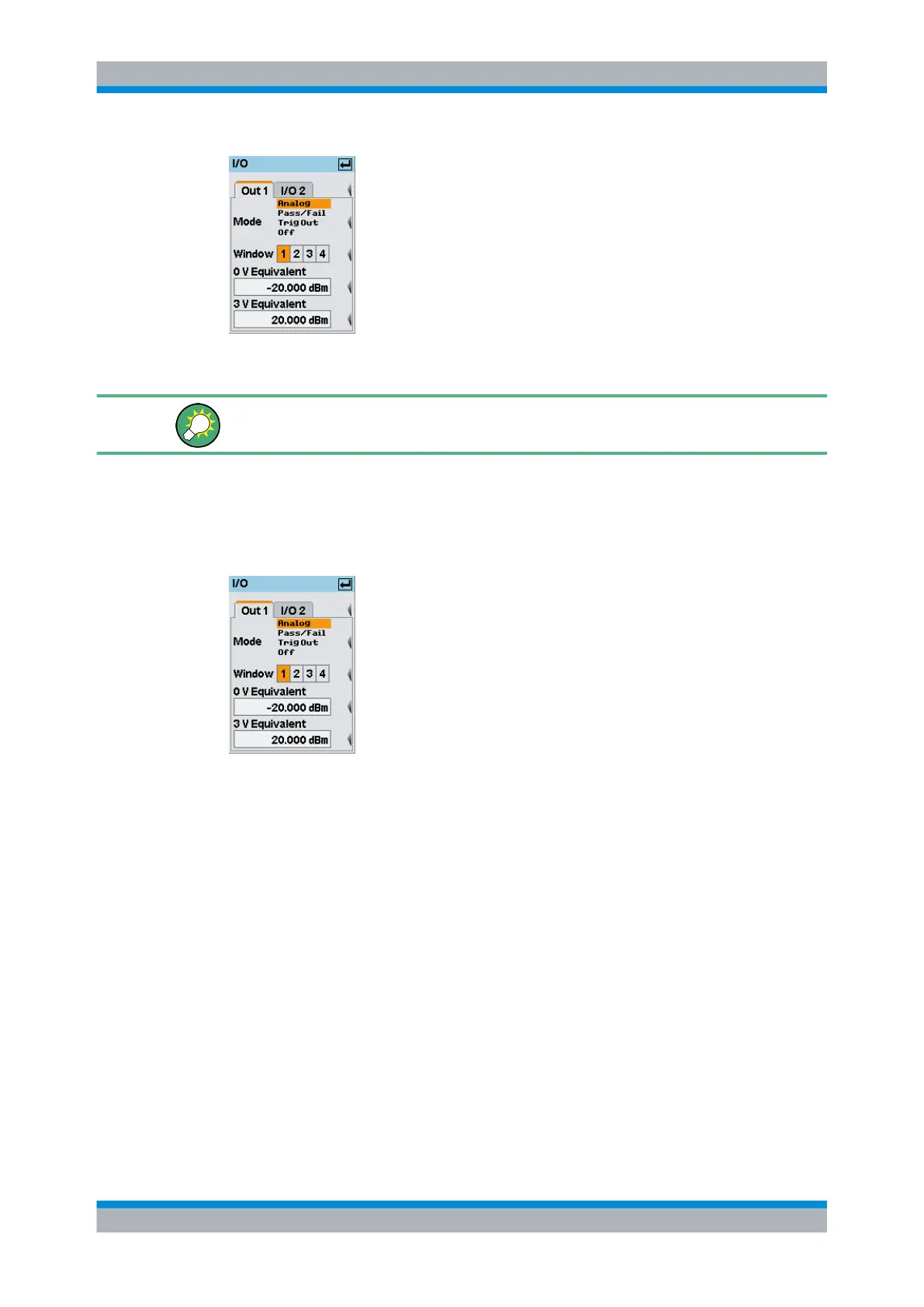
Fig. 4-81: I/O dialog box / Out1 tab
Mode
Selects the function of the "OUT1 / TRIG OUT" connector. "Analog", "Pass/Fail", "Trig-
Out" and "Off" are available.
Note: For remote control, only suffix 1 or no suffix is allowed in the command header for
the setting the OUT 1 / TRIG OUT connector functions.
Analog ← Mode
The output provides an analog voltage which is proportional to the value displayed in the
selected window, e.g. "Window 1".
System settings
 Loading...


