Instrument Functions
R&S
®
NRP2
155User Manual 1173.9157.02 ─ 03
0 V Equivalent - Analog ← Analog Out ← Mode
Entry of the measurement value that corresponds to the output voltage of 0 V.
SCPI command:
OUTPut:RECorder<[1]..2>:LIMit:LOWer on page 254
OUTPut:RECorder<[1]..2>:LIMit:LOWer:POWer on page 254
OUTPut:RECorder<[1]..2>:LIMit:LOWer:RATio on page 254
3 V Equivalent - Analog ← Analog Out ← Mode
Entry of the measurement value that corresponds to the output voltage of 3 V.
SCPI command:
OUTPut:RECorder<[1]..2>:LIMit:UPPer on page 255
OUTPut:RECorder<[1]..2>:LIMit:UPPer:POWer on page 255
OUTPut:RECorder<[1]..2>:LIMit:UPPer:RATio on page 255
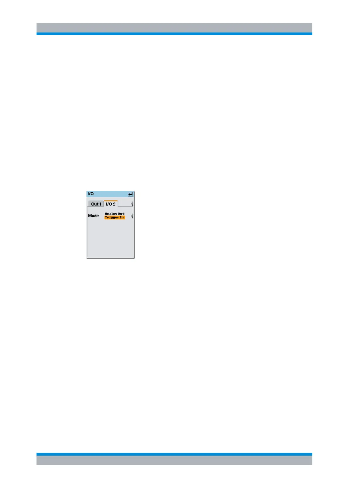
Trigger In ← Mode
The connector is used as input. An external trigger signal can be applied.
Fig. 4-88: I/O 2 mode / Trigger In
Use the external trigger signal, e.g. to start the measurement in all sensors simultane-
ously. Provided the R&S NRP2 is configured accordingly, it passes the signal directly
through to the sensors. Refer to chapter 4.2.6, "Trigger settings", on page 85 for infor-
mation on the respective settings.
SCPI command:
The state must be set to OFF.
OUTPut:RECorder<[1]..2>[:STATe] on page 256
4.7.2.3 Voltage at the analog outputs
The voltage at the analog outputs does not track the power fed to the sensor continuously
but rather at discrete points of time. Every time the sensor has transmitted a new mea-
sured value to the base unit, i.e. after an aquisition has been completed (chapter 4.2.3,
"Filter / averaging", on page 79), the analog output voltage is adjusted to the new value.
In the ContAv mode, you can influence the rate at which the voltage is updated by setting
the aperture time to a convenient value, see chapter 4.2.1.2, "Continuous average-power
measurements", on page 66. The time between two updates of the output voltage is
approximately twice the length of the aperture time. The lower limit of this length of time,
during which the R&S NRP2 can still regularly update the output voltage, depends on the
System settings
 Loading...


