Instrument Functions
R&S
®
NRP2
154User Manual 1173.9157.02 ─ 03
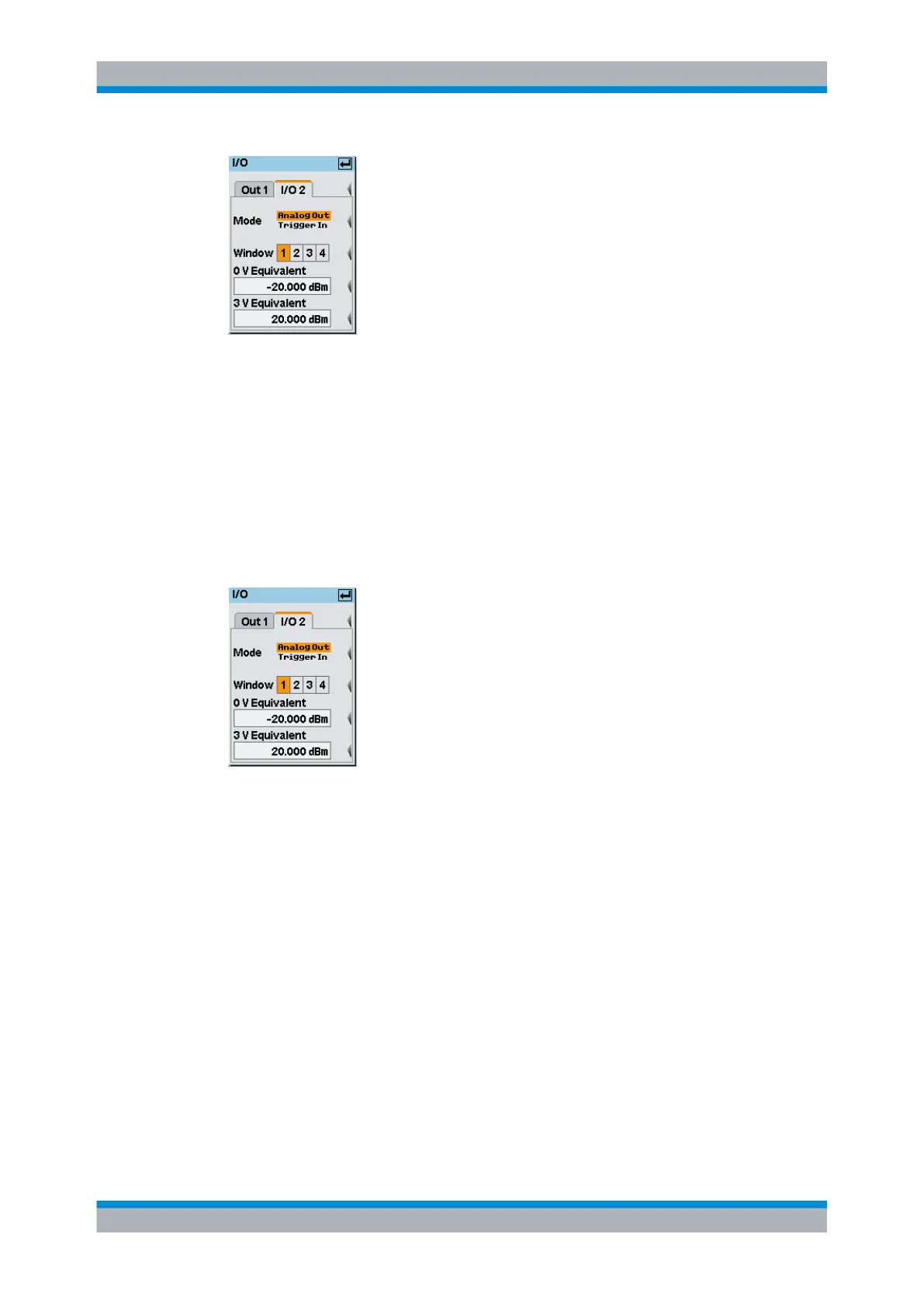
Fig. 4-86: I/O / I/O 2 tab
Mode
Selects the function of the TRIG IN / OUT2 connector. "Analog Out" and "Trigger In" are
available.
Note: For remote control, only suffix 2 is allowed in the command header for the setting
theTRIG IN / OUT2 connector functions.
Analog Out ← Mode
The output provides an analog voltage, which is proportional to the value displayed in the
selected window, e.g. "Window 1".
Fig. 4-87: I/O 2 mode / Analog Out
SCPI command:
The state must be set to ON.
OUTPut:RECorder<[1]..2>[:STATe] on page 256
Window 1 2 3 4 ← Analog Out ← Mode
Selects the window the output refers to.
Only windows that are operated in "Dig" or "D&A" window mode are available for selec-
tion. See chapter 4.3.3.3, "Selecting the result display mode", on page 93 for the setting
the display mode.
SCPI command:
OUTPut:RECorder<[1]..2>:FEED on page 253
System settings
 Loading...


