Instrument Functions
R&S
®
NRP2
64User Manual 1173.9157.02 ─ 03
This error is often caused by zeroing without switching off the test signal. If this is not the
cause, the sensor might have a hardware defect.
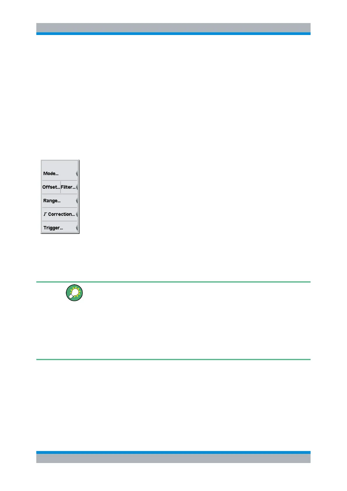
4.2 Data acquisition and parameters
Depending on the options that have been installed, up to four sensors can be connected
to the R&S NRP2. The sensors perform the complete power measurement from the
acquisition of the RF signal to every aspect of result processing. All important parameters
for configuring data acquisition are therefore entered in the "Sensor" menu. The sensor
menu provides access to all parameters concerning sensor settings like measuring mode,
filter, offset, gamma correction, level range and trigger settings.
The Sensor menu contains the following items:
● Setting the measurement mode, on page 64
● Offset correction, on page 76 and Filter/averaging, on page 79
● Measurement ranges, on page 82
● Effect of the RF source, on page 84
● Trigger settings, on page 85
● Trigger sequence control, on page 89
Some of the parameters listed above are not available for certain types of sensor.
4.2.1 Setting the measurement mode
The measurement mode is selected and configured in the "Mode" dialog box.
Regarding power measurement modes, find some background information to the follow-
ing topics at the end of this section (see chapter 4.2.1.7, "Background information on
power measurement", on page 72):
● "Acquisition interval" on page 72.
● "Dropout tolerance" on page 74
● "Smoothing modulated signals" on page 74
● "Timing diagram of burst signals" on page 74
● "Timing diagram of T'Slot Av signals" on page 75
4.2.1.1 Mode dialog box
► Select "Mode..." in the "Sensor" menu.
Data acquisition and parameters