Remote Control - Commands
R&S
®
NRP2
256User Manual 1173.9157.02 ─ 03
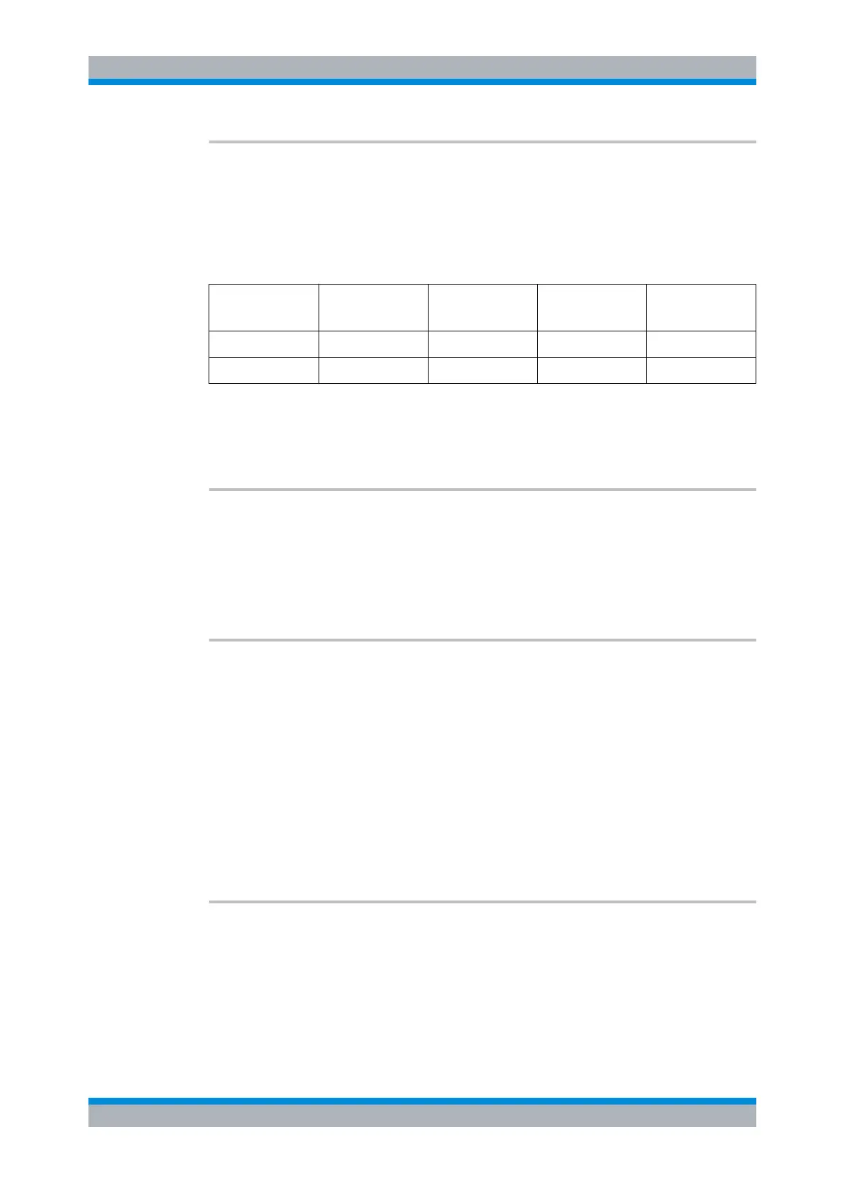
OUTPut:RECorder<[1]..2>[:STATe] <state>
Switches the analog outputs (OUT1 and OUT2/TRIG on rear panel) ON or OFF. The
magnitude of the output voltage (0 V to 3.3 V) depends on the measured power of the
assigned calculate block (OUTP:REC:FEED) and the configuration of the characteristic
(OUTP:REC:LIM). As in manual operation, this setting is coupled to other operating
modes of the outputs. Only one mode can be active at any one time:
Connector Analog output
(OUTP:REC)
TTL output
(OUTP:TTL)
Off Ext. Trigger In
OUT1 x x x -
OUT2/TRIG x - - x
Parameters:
<state> ON | OFF
*RST: output 1: ON; output 2: OFF
OUTPut:ROSCillator[:STATe] <state>
The command switches the optional RF generator (ON) or (OFF).
Parameters:
<state> ON | OFF
*RST: OFF
OUTPut:ROSCillator:CALibration:READ? <NR1>
Reads the setting of one of the internal electronic potentiometers of the test generator.
The number of the potentiometer (1 to 4) is indicated with the parameter <NR1>. The
response is an 8-bit integer with a sign (-128 to 127).
Query parameters:
<NR1> 1...4
Return values:
Setting 8-bit integer
Usage: Query only
Options: R&S NRP2-B1
OUTPut:ROSCillator:CALibration:WRIte <NR1>,<NR1>
Sets the test generator.
OUTPut
 Loading...


