Putting into Operation
R&S
®
NRP2
14User Manual 1173.9157.02 ─ 03
The cursor-key functions are context-sensitive. They are used to:
●
select a menu
●
select the active window
●
move the cursor in text boxes
●
change the value of an entry in a text box
●
select an element from a drop-down list
Except of moving the cursor, the above mentioned functions can also be activated using
softkeys.
1.5.3 On/Standby key and standby LEDs
The standby LEDS and the ON/STANDBY key are located in the bottom right corner of
the front panel. The ON/STANDBY key toggles the R&S NRP2 between standby and
ready state, indicated by the standby LEDs.
The standby LEDs indicate the current instrument state:
●
Yellow LED (AC supply)
The yellow LED indicates that the R&S NRP2 is power supplied and in standby mode.
●
Green LED (ON)
The green LED indicates when the meter on, i.e. ready for operation.
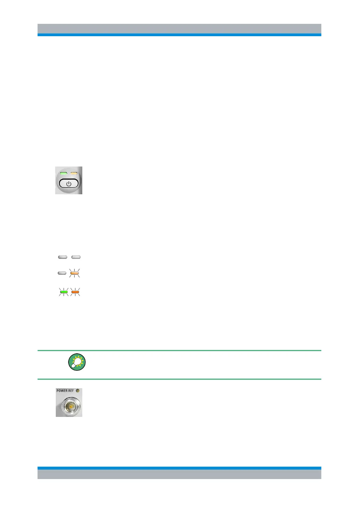
The possible operating states are:
The meter is off and disconnected from the AC supply.
The meter is on standby. The AC supply is connected and the power supply is operating
correctly.
The meter is on and is being powered from the AC supply.
1.5.4 Connectors
To the left of the display, the R&S NRP2 provides a power reference signal connector
and two sensor connectors.
If option R&S NRP-B5 is installed, the R&S NRP2 offers two sensor ports at the rear.
Thus, you can perform measurements with a maximum of 4 connected sensors simul-
taneously.
POWER REF
The POWER REF connector (option NRP-B1, sensor check source) provides a high-
precision, unmodulated sine signal with a power of 1 mW and a frequency of 50 MHz for
checking the sensors.
Chapter " Sensor Check Source" describes how the generator is turned on and off.
Front panel tour