Putting into Operation
R&S
®
NRP2
10User Manual 1173.9157.02 ─ 03
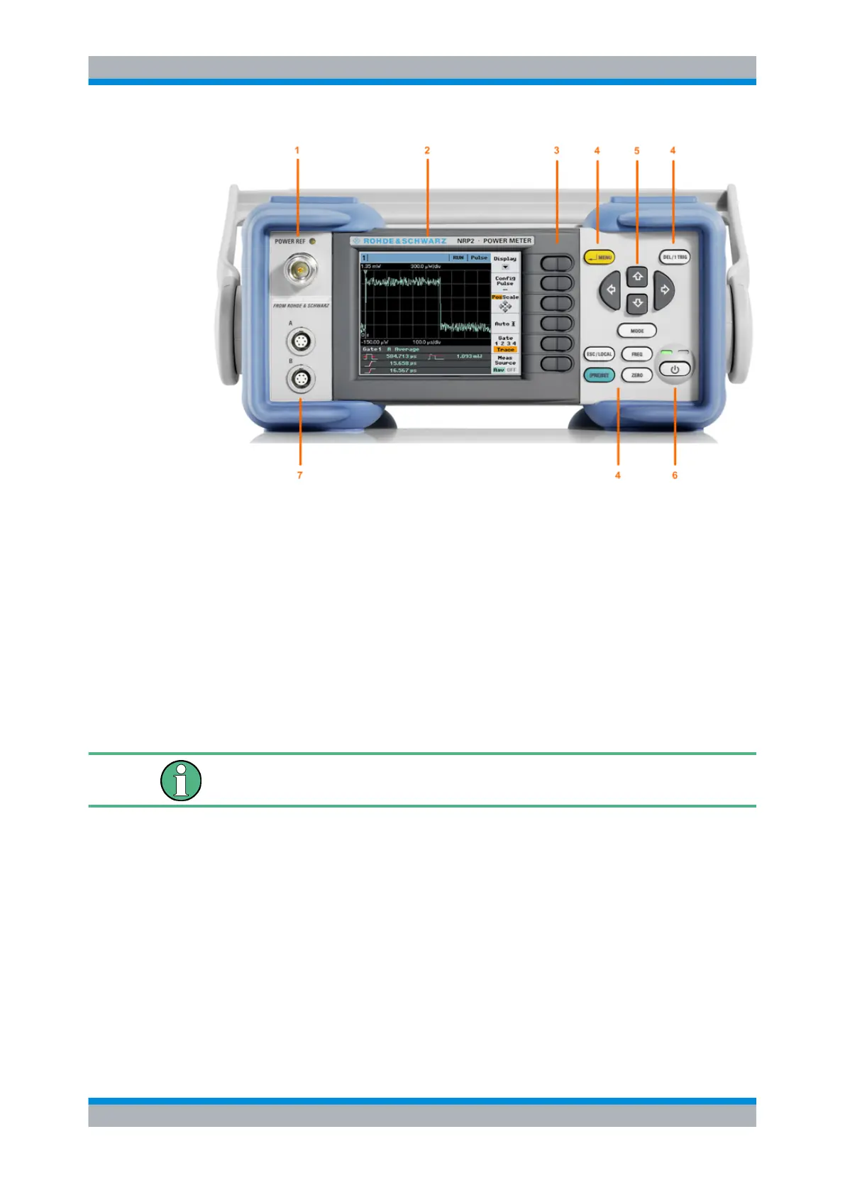
Fig. 1-1: Front panel view
1 = POWER REF connector
2 = Display
3 = Softkeys
4 = Hardkeys
5 = Cursor keys
6 = On/Standby key and standby LEDs
7 = Sensor connectors
1.5.1 Display
The R&S NRP2 displays results in windows. Depending on the measurement mode,
values are displayed digitally, in a combined digital and analog mode, or graphically.
The display mode can be selected individually for each measurement, i.e. you can per-
form both graphical and numerical representations simultaneously.
Front panel tour