Remote control interfaces
R&S
®
NRP2
350User Manual 1173.9157.02 ─ 03
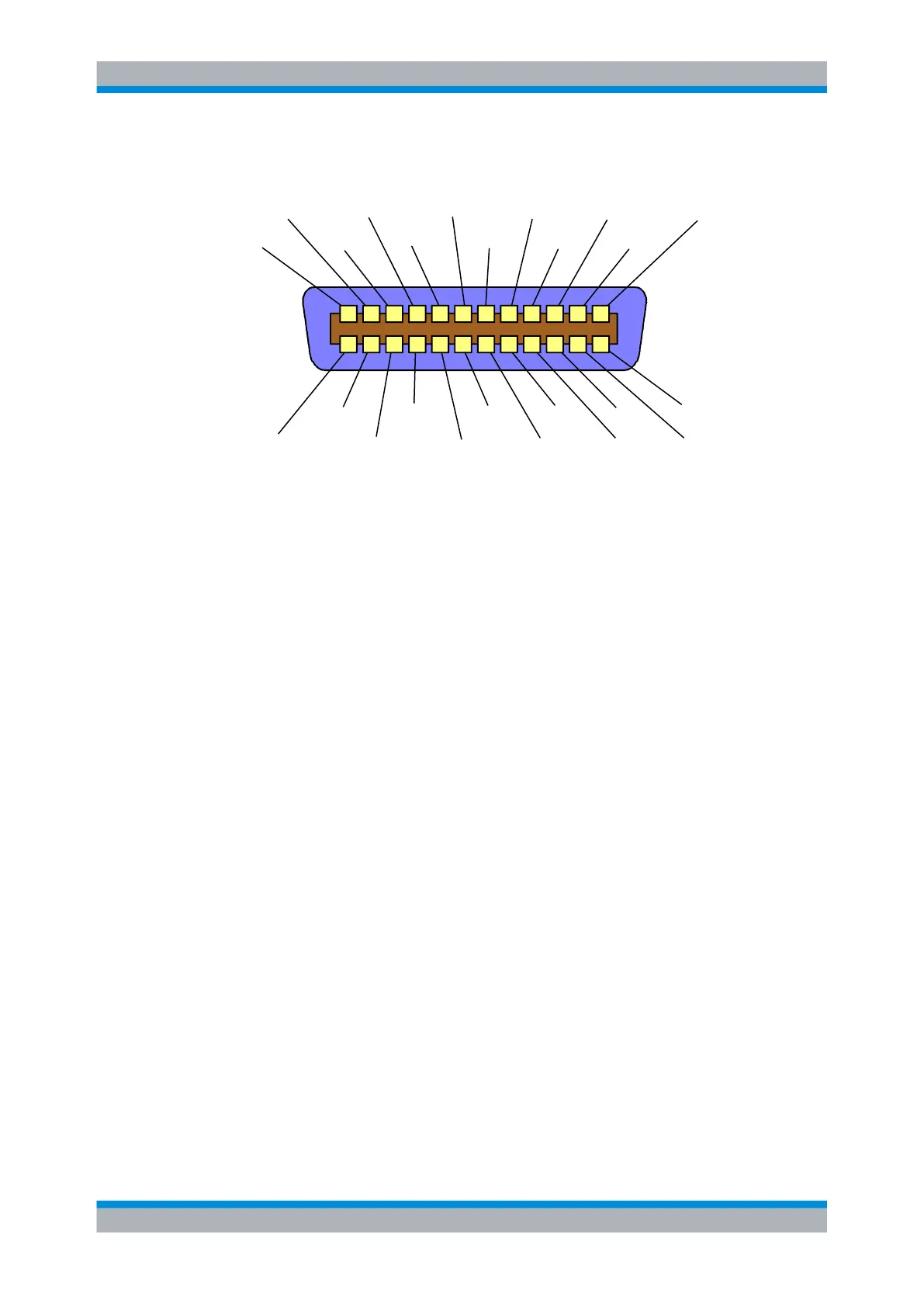
A.1.2 Pin assignment
DIO1
DIO2
DIO3
DIO4
EOI
DAV
NRFD
NDAC
IFC
SRQ
ATN
Shield
DIO7RENGND(6)logic GND GND(10) GND(8)
DIO5DIO6DIO8GND(11) GND(9) GND(7)
24 13
1415
16
1718
1920
212223
112
11 10 9
8 7 6 5 4 3 2
Fig. 1-1: Pin assignment of GPIB-bus interface
A.1.3 Bus lines
●
Data bus with 8 lines DIO1 to DIO8:
The transmission is bit-parallel and byte-serial in the ASCII/ISO code. DIO1 is the
least significant bit, DIO8 the most significant bit.
●
Control bus with five lines:
– IFC (Interface Clear):
IFC (Interface Clear)Active LOW resets the interfaces of the connected devices
to the default state.
– ATN (Attention):
Active LOW indicates the transmission of interface messages;
non-active HIGH indicates the transmission of device messages.
– SRQ (Service Request):
Active LOW enables a device to send a service request to the controller.
– REN (Remote Enable):
Active LOW permits switchover to remote control.
– EOI (End or Identify):
Has two functions in connection with ATN:
ATN = HIGH: active LOW marks the end of data transmission
ATN = LOW: active LOW triggers a parallel poll.
●
Handshake bus with three lines:
– DAV (Data Valid):
Active LOW signals a valid data byte on the data bus.
– NRFD (Not Ready For Data):
Active LOW signals that one of the connected devices is not ready for data trans-
fer.
– NDAC (Not Data Accepted):
Active LOW until the connected device has accepted the data on the bus.
GPIB Bus Interface