Getting Started
R&S
®
NRP2
45User Manual 1173.9157.02 ─ 03
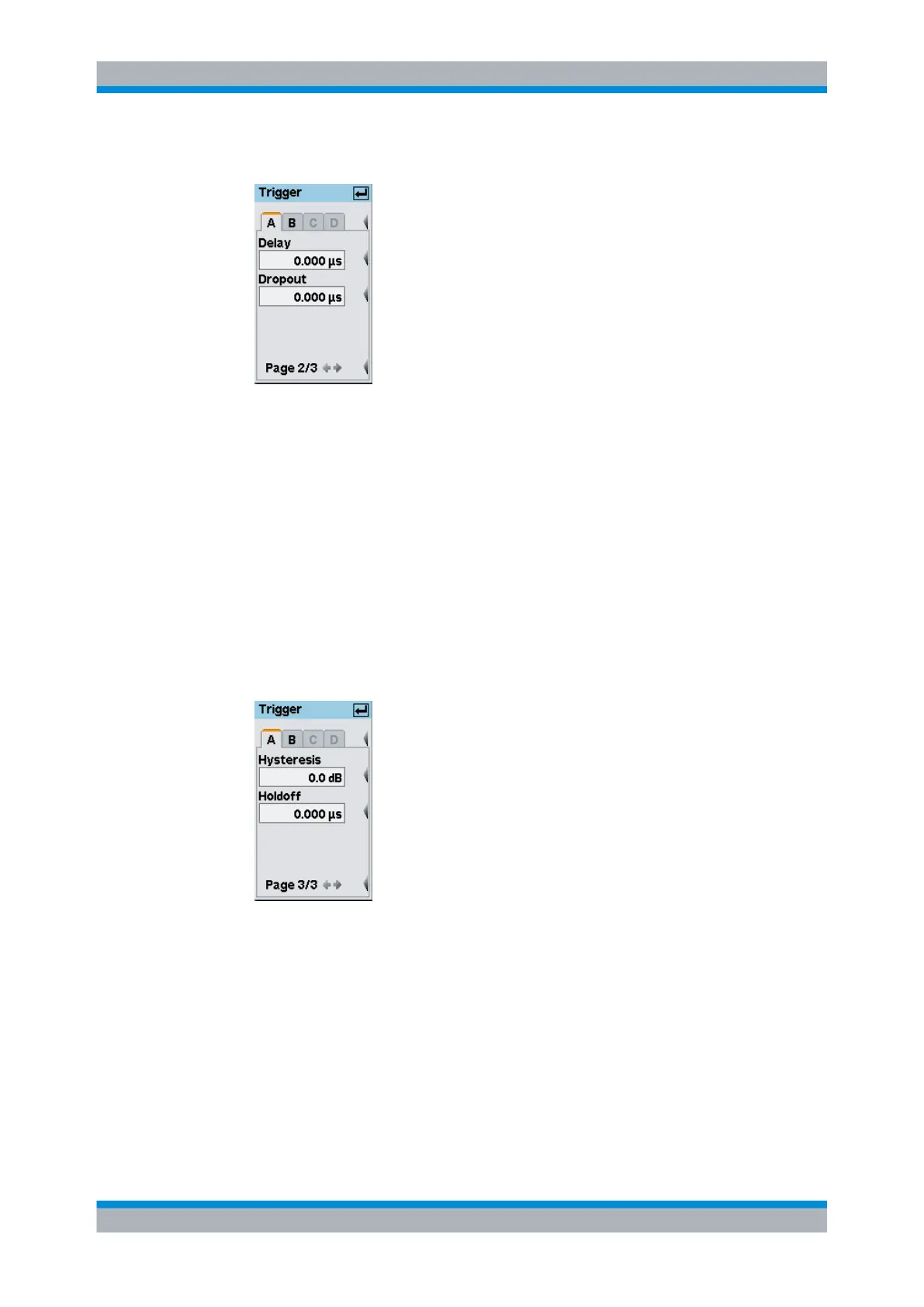
6. Open the second page of the "Trigger" dialog box.
Fig. 2-36: Trigger dialog box / page 2
7. Set the trigger delay time. If you set a positive value, the trigger event will become
effective only after the selected period of time. The displayed trace will be shifted to
the left.
In the "Trace & Statistics" display, the physical and the delayed trigger time has been
made visible in the form of small triangles, thus allowing an interactive adaptation of
the "Delay" parameter to the signal, see chapter 3.6.2, "Special symbols",
on page 58.
8. Enter a "Dropout" value.
The dropout time prevents the trigger system from being activated by signal excur-
sions prior to the trigger event targeted.
9. Scroll to the third page of the "Trigger" dialog box.
Fig. 2-37: Trigger dialog box / page 3
10. Set a "Hysteresis" value.
Setting the trigger hysteresis to a value other than 0 dB will prevent triggering from
occurring again until the measurement level has fallen below the trigger threshold by
at least this value.
11. Define a "Holdoff" time.
This parameter allows you to set the period of time during which further trigger events
(measured from the last successful triggering) should be ignored.
Graphically representing power versus time