12. Timer B
puorG92/C61M
page 122
854fo7002,03.raM21.1.veR
2110-1010B90JER
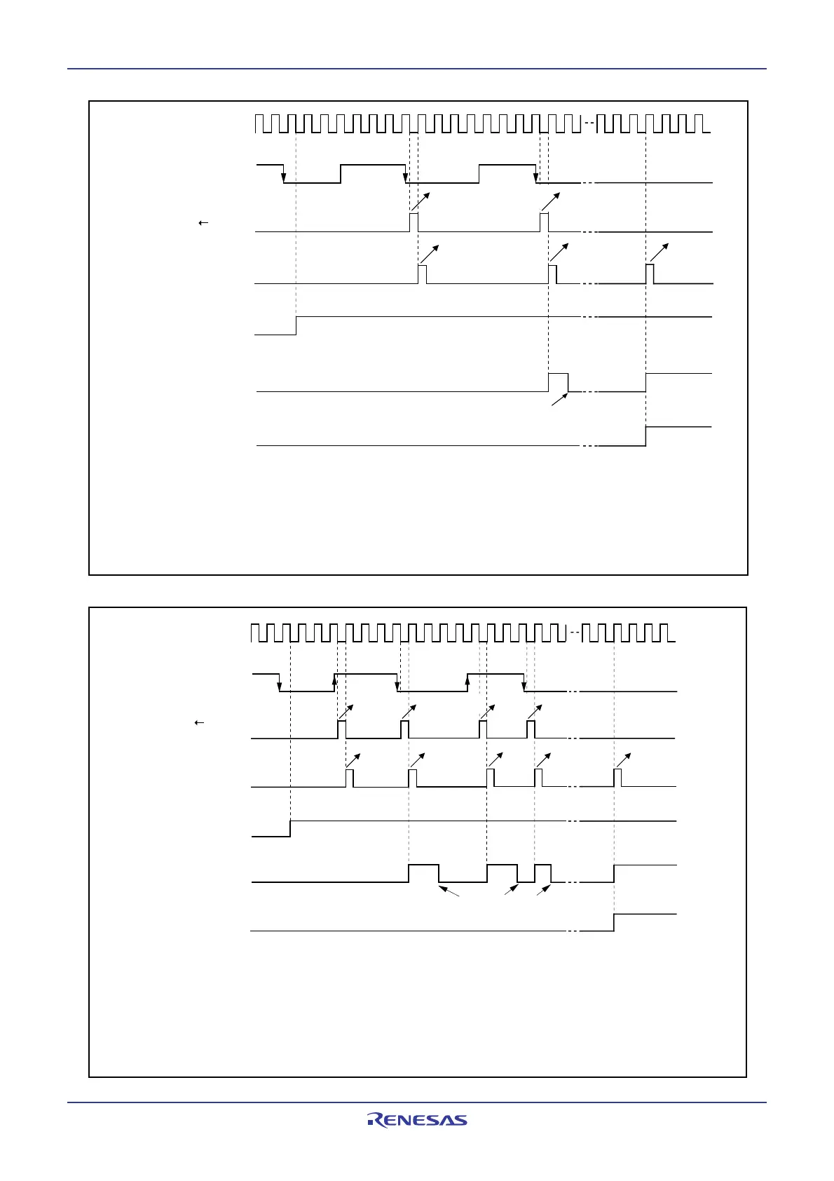
Figure 12.22 Operation timing when measuring a pulse width
Figure 12.21 Operation timing when measuring a pulse period
Count source
Measurement pulse
TBiS bit
TBiIC register's
IR bit
Timing at which counter
reaches 0000
16
“H”
1
Transfer
(undefined value)
“L”
0
0
TBiMR register's
MR3 bit
1
0
NOTES:
1. Counter is initialized at completion of measurement.
2. Timer has overflowed.
3. This timing diagram is for the case where bits MR1 and MR0 in the TBiMR register are 00
2
(measure the
interval from falling edge to falling edge of the measurement pulse).
(1)(1)
(2)
Transfer
(measured value)
1
Reload register counter
transfer timing
Bits TB0S to TB2S are assigned to the bit 5 to bit 7 in the TABSR register.
Set to 0 upon accepting an interrupt request or by program
i = 0 to 2
Measurement pulse
“H”
Count source
Timing at which counter
reaches 0000
16
1
1
Transfer
(measured value)
Transfer
(measured value)
“L”
0
0
1
0
(1)(1)(1)
Transfer
(measured
value)
(1)
(1)
Transfer
(undefined
value)
Reload register counter
transfer timing
TBiS bit
TBiIC register's
IR bit
The MR3 bit in the
TBiMR register
NOTES:
1. Counter is initialized at completion of measurement.
2. Timer has overflowed.
3. This timing diagram is for the case where bits MR1 to MR0 in the TBiMR register are 10
2
(measure the interval
from a falling edge to the next rising edge and the interval from a rising edge to the next falling edge of the
measurement pulse).
Bits TB0S to TB2S are assigned to the bit 5 to bit 7 in the TABSR register.
Set to 0 upon accepting an interrupt request or by
program
i = 0 to 2
 Loading...


